After getting thoroughly destroyed, twice, at November Necrosis, I wanted to spend some time improving Drop Test with the free time I had over the holidays. As a reminder from that post here are the main conclusions I had after that event:
With these goals in mind, I started my redesign. I finally had access to Solidworks again, so I was planning to move the old assembly from OnShape to Solidworks, but with so many things changing, it was easier just to start from scratch with the learnings I had in mind.
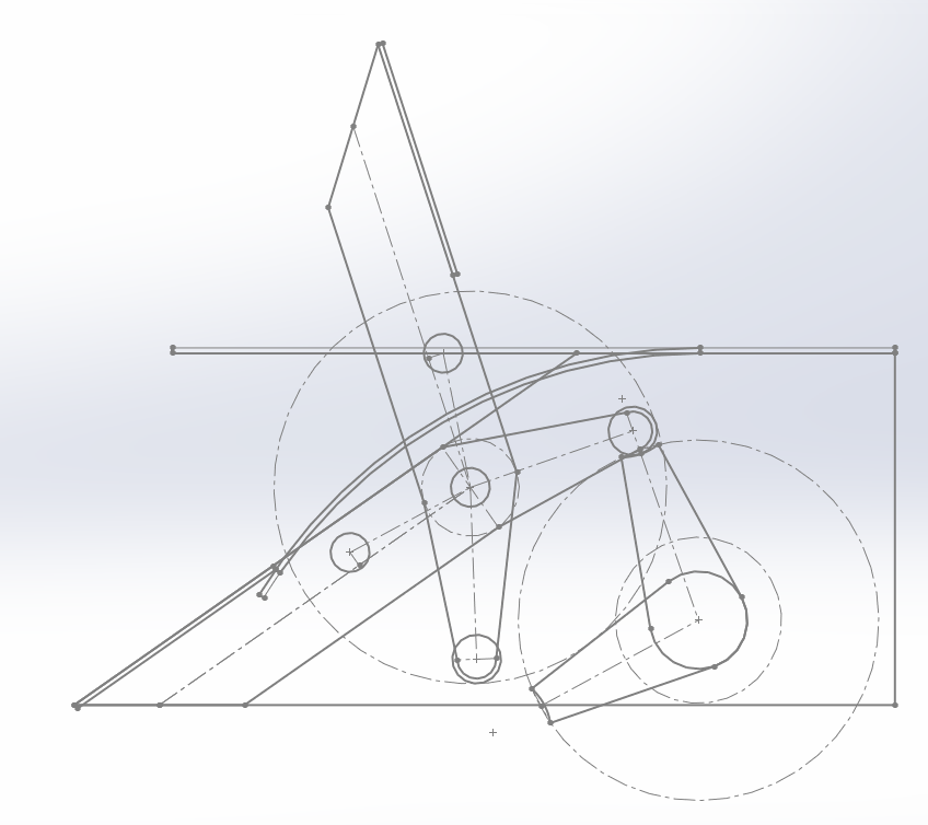
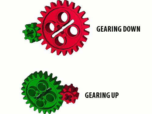
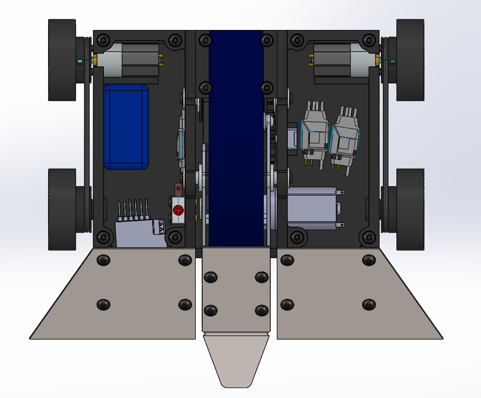
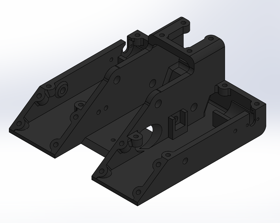
As with the first version of Drop Test, I started the design with a general layout sketch. The overall flipper design worked well in its first competition, but needed some tweaks to help improve. First, I wanted to shorten the overall robot to make it more compact so that I could increase the durability of the 3D printed frame. This meant increasing the angle of the wedge slightly to compensate. This meant moving things around slightly to maintain the same overall working principle. As you can see in the picture below, as a result of this re-shuffling of components, the trigger mechanism (below left, right side) is fully contained within the bot instead of sticking out of the rear of the bot like it did in the first version. This shortening also meant that the leaf spring was shorter and had a greater tip deflection when the flipper was fully loaded. Without going into the details too much, this should create a higher flipping force than the original design as well. Finally, I realized that the original layout of the trigger mechanism was highly inefficient mechanically. The main issue was that the trigger had a roller on it that acted as a pseudo cam follower to ride along the backside of the flipper arm to load the mechanism. I realized that if I switched the follower to the flipper arm side it would be more efficient and closer to a traditional snail cam design. Essentially, if you imagine the pair of rotating arms as gears instead, with the roller on the trigger, the driving gear had a fixed, large diameter that would result in a "gearing down" scenario which produces more speed and less torque. Instead what I wanted was a "gearing up" scenario where the roller, now on the flipper arm, contacts the trigger arm near the pivot point, such that there is a much smaller torque arm, similar to a small driving gear. This change should allow me to use a lower gear reduction on the flipper motor to allow for a quicker reset time overall. For more information on the math behind all this go check out the original post.
- The flipper worked, but it could definitely be better. Should be more powerful and easier to control
- Maintain designing for repairs by using connectors, making things easy to replace, and build spares
- Make 3D printed frame more durable by changing print orientation and making walls thicker, especially up front
- Make it easier to get opponents on to the flipper/wedge for better control
With these goals in mind, I started my redesign. I finally had access to Solidworks again, so I was planning to move the old assembly from OnShape to Solidworks, but with so many things changing, it was easier just to start from scratch with the learnings I had in mind.
As with the first version of Drop Test, I started the design with a general layout sketch. The overall flipper design worked well in its first competition, but needed some tweaks to help improve. First, I wanted to shorten the overall robot to make it more compact so that I could increase the durability of the 3D printed frame. This meant increasing the angle of the wedge slightly to compensate. This meant moving things around slightly to maintain the same overall working principle. As you can see in the picture below, as a result of this re-shuffling of components, the trigger mechanism (below left, right side) is fully contained within the bot instead of sticking out of the rear of the bot like it did in the first version. This shortening also meant that the leaf spring was shorter and had a greater tip deflection when the flipper was fully loaded. Without going into the details too much, this should create a higher flipping force than the original design as well. Finally, I realized that the original layout of the trigger mechanism was highly inefficient mechanically. The main issue was that the trigger had a roller on it that acted as a pseudo cam follower to ride along the backside of the flipper arm to load the mechanism. I realized that if I switched the follower to the flipper arm side it would be more efficient and closer to a traditional snail cam design. Essentially, if you imagine the pair of rotating arms as gears instead, with the roller on the trigger, the driving gear had a fixed, large diameter that would result in a "gearing down" scenario which produces more speed and less torque. Instead what I wanted was a "gearing up" scenario where the roller, now on the flipper arm, contacts the trigger arm near the pivot point, such that there is a much smaller torque arm, similar to a small driving gear. This change should allow me to use a lower gear reduction on the flipper motor to allow for a quicker reset time overall. For more information on the math behind all this go check out the original post.
 |  |
With the layout sketch complete, I started in on the actual parts design. I didn't take any picutres during the CAD process, so I will split up this section into focused reviews of system upgrades to the robot.
Wedge Design
The idea behind the original wedge design on the original bot was to help protect the delicate flipper mechanism from horizontal spinners. The dual angled face of the wedges would theoretically deflect any incoming blows from spinners. This idea worked (until the 3D printed body that the wedges attached to snapped in half), but provided additional issues. Mostly it made it very difficult for me to control y opponents and line up the flipper as they would usually just slide off of the side of the bot when I tried to push them up on the wedge.
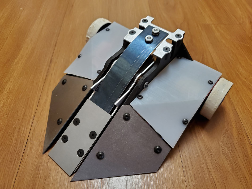
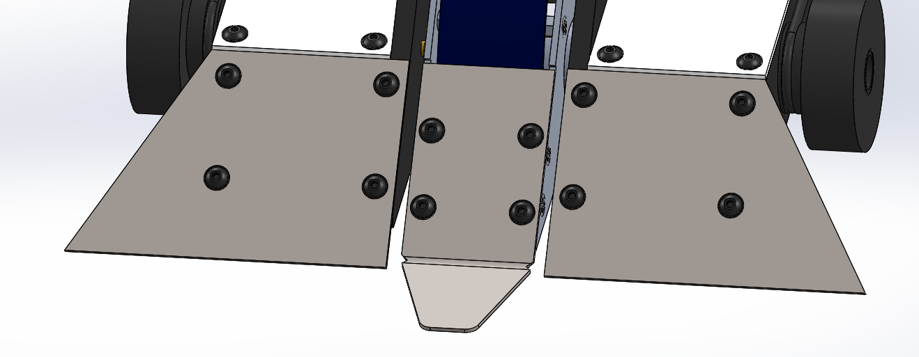
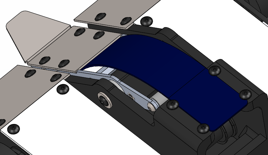
For the redesign, I opted to make things a little more simple and have a flat wedge face that spanned the whole width of the bot. Having this wide flat surface should help to control my opponents much more easily. To handle horizontal attacks, I angled the outer edges of the wedge, similar to Duck. This likely won't be as resistant to large horizontals, but should still provide some deflection to prevent the entire wedge being ripped off with minimal material. The real upgrade here is more optimally using the inner volume of the bot by changing the wedges to allow for a stronger attachment method for the wedges. Following the Battlebots upgrade theme, I wanted to have a small tongue on the end of the flipper wedge to allow me to more easily get under bots to flip them. I decided to do this by bending a flange on the end of the flipper wedge in the middle of the bot. I've tried to avoid metal bending up until this point in my designs as I don't really have the proper tools for it. This being 1mm titanium, I'm fairly confident I can bend it by hand using the tools I have well enough. To help with this process, I added two little notches in the wedge where the bend line is to be. This should help the material naturally bend along the line that I intend to bend it on. Finally, learning from my first design, I decided to forgo any countersinking on the wedges, because countersinking titanium with hand tools takes forever and only provides minimal benefit.
Drive Train
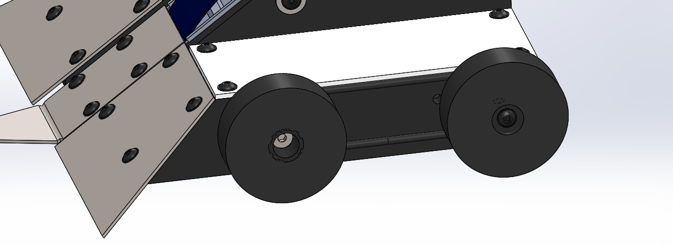
Another reason that I was having trouble controlling my opponents was the fact that the wheels were all the way at the rear of the robot. Due to the height of the robot, I was worried about the bot getting stuck on its back and not being able to self right. This meant that the wheels had to be on the rear corner of the robot to keep them in constant contact with the ground to help right myself from any orientation. With the wheels at the rear, and the robot being so long due to the flipper assembly, it was very difficult to drive and control opponents. I knew I was likely going to shift things around with this version of the robot to make it more compact, but that meant moving the COG further forward, making it even harder to drive. To prevent this issue I decided to make this version of Drop Test 4WD.
When I started this process, I realized, looking back at my previous bots, that I had never made a 4WD robot before. Whether it was due to the style of robots I had chosen, or my design style in general, I never really had weight or room for 4 wheels in my robots up until now. I knew I was going to be tight on weight again, especially considering I was trying to make the robot more durable, so 4 motors to drive 4 wheels was out of the question. I might revisit the idea in the future though as the N20 gearmotors are about half the weight of my current drive motors, although less durable.
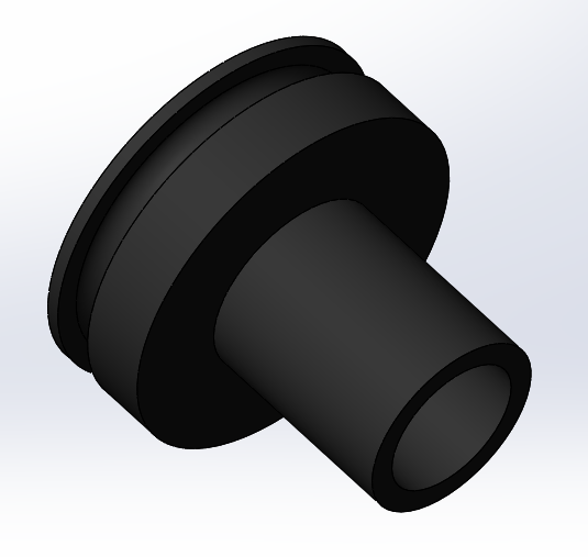
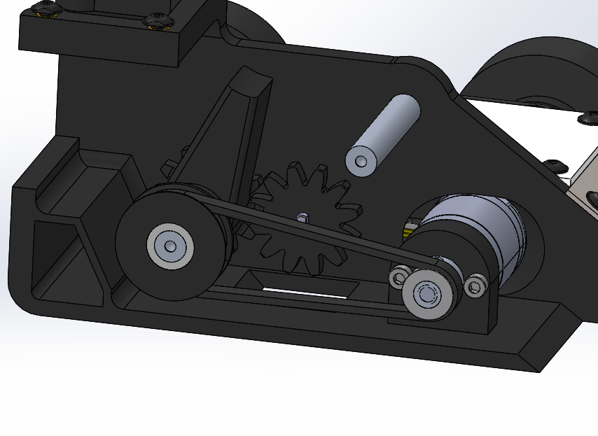
My solution for this was belt drive. The rear wheels would be connected directly to the drive motors, while the front wheels would be spinning on a dead shaft. The two sets of wheels would be connected by an O ring acting as a round belt. This required me to design my own hubs that incorporated round belt pulleys into them. Given that I was already 3D printing lots of parts for this project, it seemed easy enough to design and print my own hubs specifically for the task. Both hubs would use the Fingertech foam tires that I used in the previous version. The rear hub is based off of the original Dale's Hubs that were sold by RobotMarketplace years ago, where the main hub mounted to the motor shaft through a setscrew and an additional plate screwed into the end to secure the wheel to the hub. The front hub would ride on a shoulder bolt that would act as a dead shaft for the hub to spin on. For this hub, since I can't screw on an additional plate to secure the wheel, I intend to simply glue the wheel to the hub and treat them both as disposable since they are cheap enough. Both hubs include a pulley feature to hold a 3/32" O ring that is stretched 15% past nominal to tension the belt to the point that it will drive the front wheels. I'm not entirely confident this system will work as intended, but for a first go at a custom belt driven wheel solution I think it's good enough to build to test out.
When I started this process, I realized, looking back at my previous bots, that I had never made a 4WD robot before. Whether it was due to the style of robots I had chosen, or my design style in general, I never really had weight or room for 4 wheels in my robots up until now. I knew I was going to be tight on weight again, especially considering I was trying to make the robot more durable, so 4 motors to drive 4 wheels was out of the question. I might revisit the idea in the future though as the N20 gearmotors are about half the weight of my current drive motors, although less durable.
My solution for this was belt drive. The rear wheels would be connected directly to the drive motors, while the front wheels would be spinning on a dead shaft. The two sets of wheels would be connected by an O ring acting as a round belt. This required me to design my own hubs that incorporated round belt pulleys into them. Given that I was already 3D printing lots of parts for this project, it seemed easy enough to design and print my own hubs specifically for the task. Both hubs would use the Fingertech foam tires that I used in the previous version. The rear hub is based off of the original Dale's Hubs that were sold by RobotMarketplace years ago, where the main hub mounted to the motor shaft through a setscrew and an additional plate screwed into the end to secure the wheel to the hub. The front hub would ride on a shoulder bolt that would act as a dead shaft for the hub to spin on. For this hub, since I can't screw on an additional plate to secure the wheel, I intend to simply glue the wheel to the hub and treat them both as disposable since they are cheap enough. Both hubs include a pulley feature to hold a 3/32" O ring that is stretched 15% past nominal to tension the belt to the point that it will drive the front wheels. I'm not entirely confident this system will work as intended, but for a first go at a custom belt driven wheel solution I think it's good enough to build to test out.
 |  |
Flipper Upgrades
While the first version of Drop Test achieved my goals of successfully flipping a bot in combat, it had it's flaws. Due to my underestimation of the power required to load the intended flipping mechanism, and weight constraints, I had to sacrifice flipping power to make everything work. As a result, the flips that it was able to dish out were more of quick lifts than launching my opponent like I wanted. I also switched from a servo motor to a regular brushed DC gearmotor to be able to have more power for the same weight. This gave me more flipping power, but at the cost of not knowing the absolute position of the trigger mechanism. This meant I had multiple misfires in the arena leading me to defensively driving around while I reset the flipper, instead of attacking and controlling my opponent.
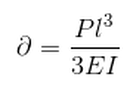
To fix the flipping force issue, as I mentioned before, I decreased the length of the spring while increasing the deflection. Looking at the equation below we can see that this should increase the force at the end of the spring, leading to a greater flipping power.
To fix the flipping force issue, as I mentioned before, I decreased the length of the spring while increasing the deflection. Looking at the equation below we can see that this should increase the force at the end of the spring, leading to a greater flipping power.
 | 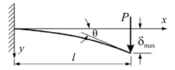 |
The other spring related upgrade that was made was to remove the mounting holes from the spring and instead, hold the spring at it's edges with screws. This is because spring steel is really hard and very difficult to cut holes in without the proper equipment. This removed the need for the spring mounting plate as well, freeing up some weight for the rest of the upgrades.
To address the issue of the trigger positioning, I revisited the original design log for this robot. The original idea was to use a servo to power the flipper such that, when using a self centering stick on a transmitter, one direction would be to fire the flipper, and the other would be to reload the flipper, with the self centering position being the loaded position. I was unable to find a servo with enough power for my needs that wouldn't weigh so much that it would be detrimental to the rest of the robot. At the time, I really liked the idea of using the servo controller to control the output after the gear reduction, similar to how servo gearboxes work. It was very difficult to design though, without the parts on hand to measure and integrate into the design. And with all of the other difficulties I had with the initial design, that idea got pushed.
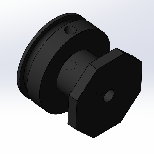
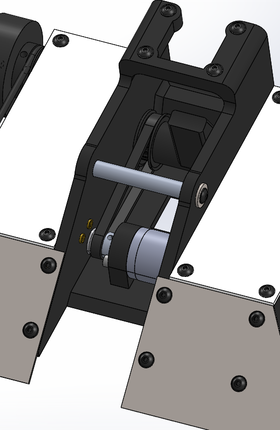
Now, having a programmable servo on hand that I could take apart to use for my needs, and having the motor setup already established, it would be much easier to incorporate. In this version of the bot, I wanted to change the trigger drivetrain from metal gears to timing belts to save weight and allow me to re-organize the internals of the robot. As you can see below, I had already designed the trigger to be 3D printed with an integrated timing pulley. This allowed me lots of flexibility in the design and positioning of my servo feedback system. Because the trigger shaft was now a dead shaft, the easiest way for me to connect the potentiometer to the trigger was through a pair of equal sized gears. One integrated into the trigger, and one attached to the potentiometer. This was the servo control board that I salvaged from a servo would know the direct position of the output arm as intended.
Now, having a programmable servo on hand that I could take apart to use for my needs, and having the motor setup already established, it would be much easier to incorporate. In this version of the bot, I wanted to change the trigger drivetrain from metal gears to timing belts to save weight and allow me to re-organize the internals of the robot. As you can see below, I had already designed the trigger to be 3D printed with an integrated timing pulley. This allowed me lots of flexibility in the design and positioning of my servo feedback system. Because the trigger shaft was now a dead shaft, the easiest way for me to connect the potentiometer to the trigger was through a pair of equal sized gears. One integrated into the trigger, and one attached to the potentiometer. This was the servo control board that I salvaged from a servo would know the direct position of the output arm as intended.
 |  |
General Upgrades
The electronics for the robot stayed almost identical to the previous version, with the exception of the servo board replacing the TinyESC that was driving the trigger motor. The main upgrades to the body were in packaging.
I nestled the flipper motor underneath the flipper arm, allowing the whole robot to be significantly narrower. This freed up some weight to thicken up the walls of the bot for better durability. This also meant I had to move the wire run between the two sides of the bot to the rear as the front was very crowded now. I also had to get creative with the mounting and clearance for the weapon motor to allow for the frame to be printed as one piece and still be easy to install.
Finally, the robot came in at a very nice weight in CAD of 442g with the weight roughly centered over the wheels. This should allow for good mobility and leave enough weight for things like wires and latex for the wheels that aren't accounted for in CAD. It was much easier to make weight this time around with all of the lessons learned from the initial design.
 RSS Feed
