After a long hiatus of both building and attending events, I've been ramping up to attend the Smashbotz 2021 event in LA on October 16th. My goal for this event was to bring two bots: Butcher and Drop Test. Butcher because it's still mostly in tact and only required a few minor upgrades to get it going again. And Drop Test because I feel like it's really close to something special as an ant-weight spring flipper, it just needs the proper work put into it to make it happen.
Butcher 3.0
Butcher's performance had been less than stellar recently. It had two core issues:
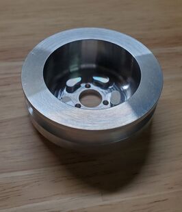
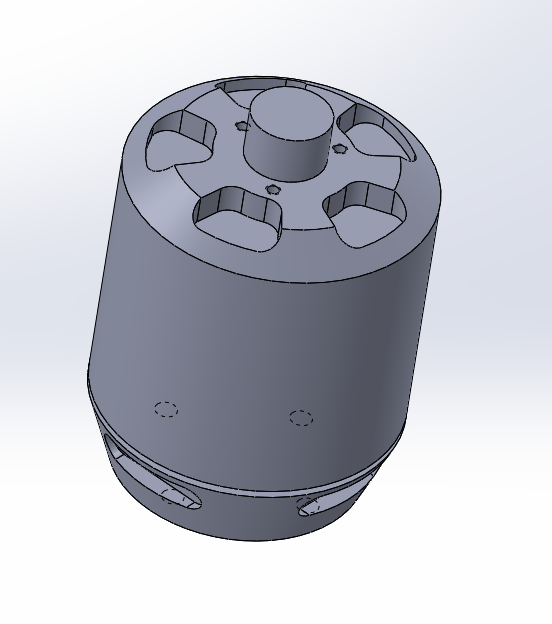
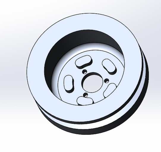
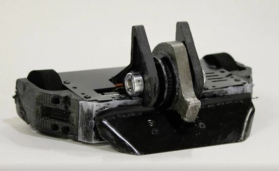
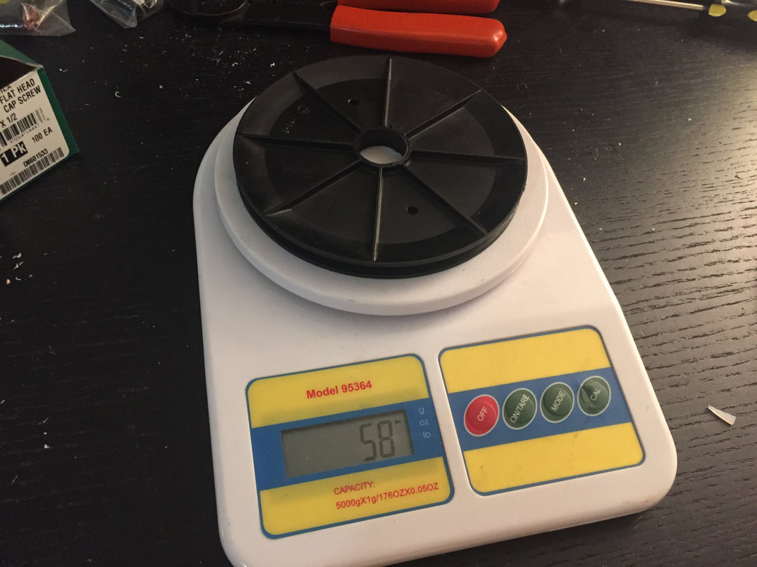
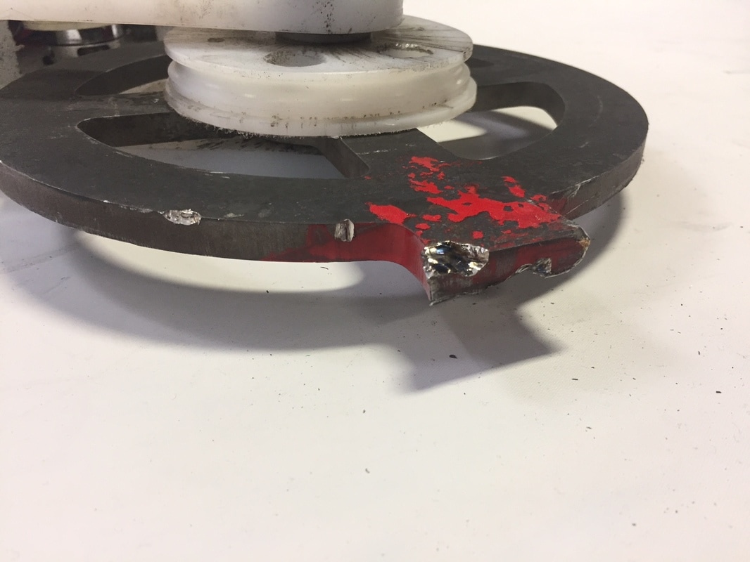
First, for the weapon system I had two parts that I changed out to make this issue hopefully disappear. First the weapon motor pulley in previous versions had a plane bore that was held on to the can by some small set screws and eventually just epoxied on there when the set screws failed. The core issue is that shock loads would get transfered back to the weapon motor from the disc when it hit something. The weapon motor in Butcher is big enough (4250 brushless outrunner) that it needs a secure attachment to make sure this joint doesn't fail. To combat this, I had a custom aluminum pulley CNC machined to perfectly fit the motor. You can see in the picutre below that there is not only a hole pattern on the top face of the pulley, to interface with the matching bolt pattern on the top face of the motor, but there is also a set of 5 bosses that are machined on the inside of that top face. These bosses slide into the cutouts in the top of the motor with a slip fit. These are designed to contact the machined body of the motor before the pulley can rotate enough to put this force on the tiny M2 screws in the face of the motor. The screws should be enough to hold the pulley onto the motor, and the machined bosses can take the shear loads from the sudden impacts meaning hopefully this pulley will never come apart from the motor.
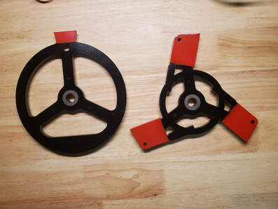
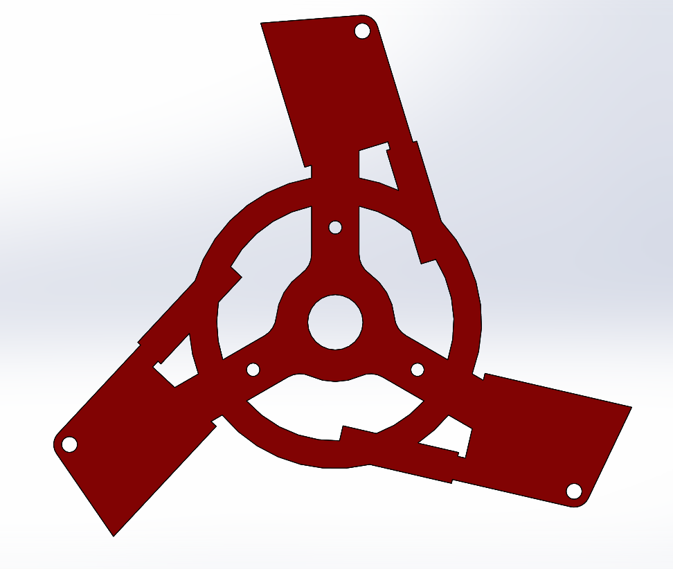
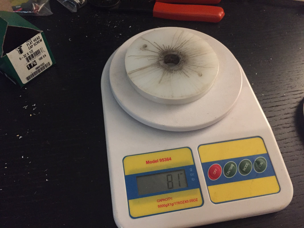
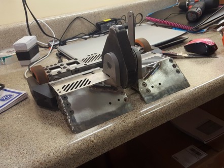
A less critical but way cooler change I made for this version of the weapon system as well is the new disc I designed. Again this is detailed in the design post linked above, but instead of the large single tooth disc that I have been running, I created a 3 tooth disc of roughly the same weight that looks like a set of spinning butcher's knives as an ode to the name of the robot. This disc not only looks way cooler, it will be nice to have as a secondary option instead of the single tooth disc. In theory this will be able to deliver smaller hits while continuing to spin as well as spin up faster given the smaller MOI. Both of these traits will be really useful in fights against some of the tank like wedge robots that are commonly found in the hobby weight class.
- The weapon motor pulley constantly decoupled from the weapon motor, especially on big impacts
- The drive motors were too small of in-runners. They were too fast and the pinions on the motors regularly came loose on the shaft
First, for the weapon system I had two parts that I changed out to make this issue hopefully disappear. First the weapon motor pulley in previous versions had a plane bore that was held on to the can by some small set screws and eventually just epoxied on there when the set screws failed. The core issue is that shock loads would get transfered back to the weapon motor from the disc when it hit something. The weapon motor in Butcher is big enough (4250 brushless outrunner) that it needs a secure attachment to make sure this joint doesn't fail. To combat this, I had a custom aluminum pulley CNC machined to perfectly fit the motor. You can see in the picutre below that there is not only a hole pattern on the top face of the pulley, to interface with the matching bolt pattern on the top face of the motor, but there is also a set of 5 bosses that are machined on the inside of that top face. These bosses slide into the cutouts in the top of the motor with a slip fit. These are designed to contact the machined body of the motor before the pulley can rotate enough to put this force on the tiny M2 screws in the face of the motor. The screws should be enough to hold the pulley onto the motor, and the machined bosses can take the shear loads from the sudden impacts meaning hopefully this pulley will never come apart from the motor.
A less critical but way cooler change I made for this version of the weapon system as well is the new disc I designed. Again this is detailed in the design post linked above, but instead of the large single tooth disc that I have been running, I created a 3 tooth disc of roughly the same weight that looks like a set of spinning butcher's knives as an ode to the name of the robot. This disc not only looks way cooler, it will be nice to have as a secondary option instead of the single tooth disc. In theory this will be able to deliver smaller hits while continuing to spin as well as spin up faster given the smaller MOI. Both of these traits will be really useful in fights against some of the tank like wedge robots that are commonly found in the hobby weight class.
 |  |
 |  |
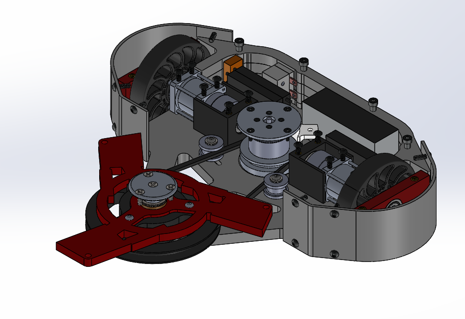
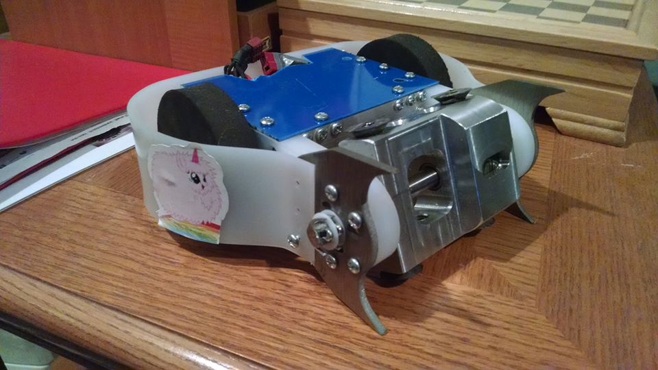
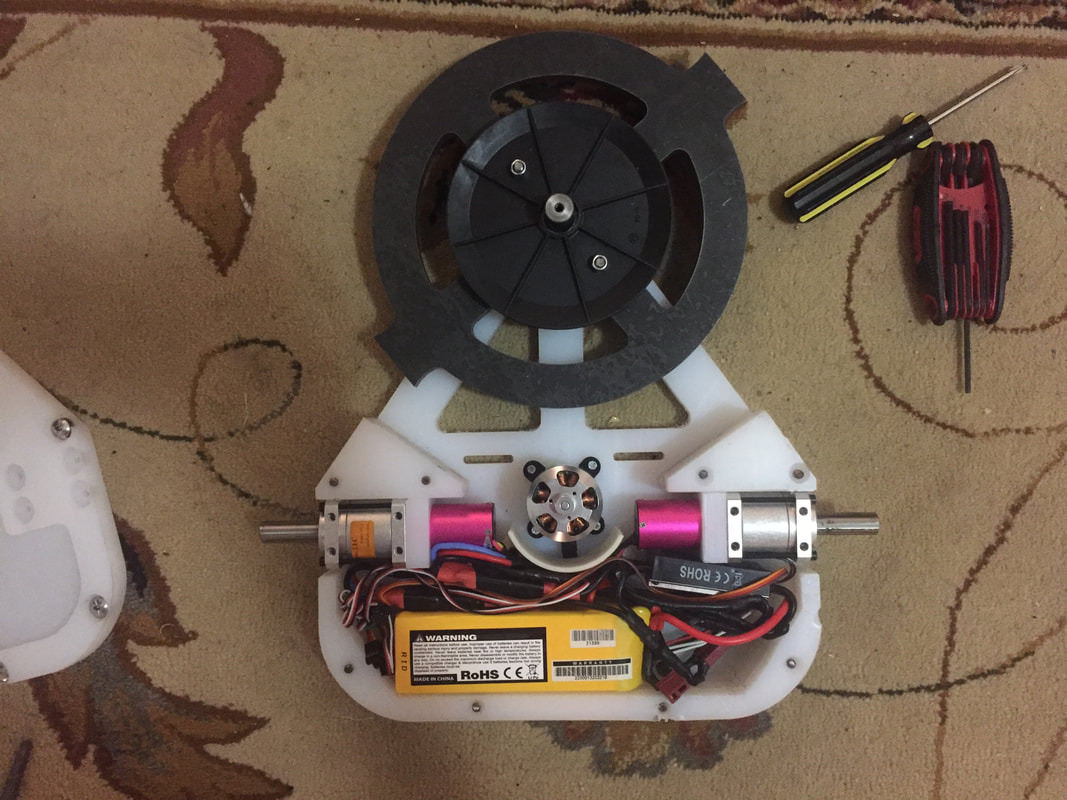
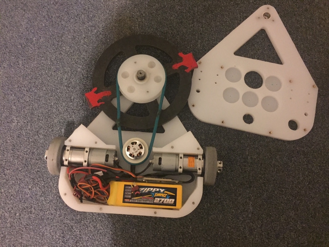
The other system that got a major upgrade was the drive train. Like I said above, the issues I was having mostly came down to the fact that I had picked inrunners for the old drive train because I didn't want to have to deal with outrunners and protecting wires from them. But after multiple events of the motors overheating and torching themselves, twitchy drive due to the high input RPM, and multiple occasions of the pinions on the 3mm shafts coming loose, I decidided an upgrade was necessary and long overdue.
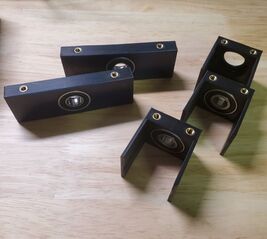
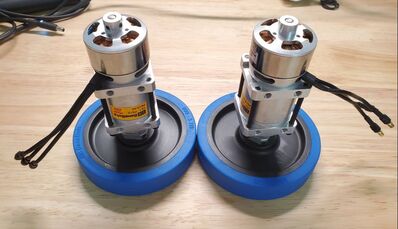
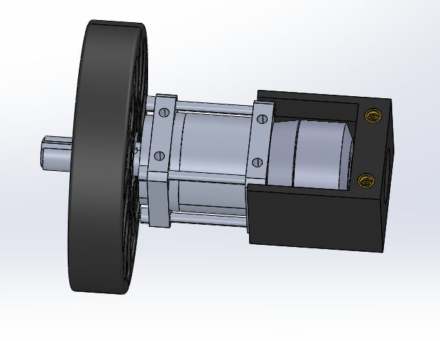
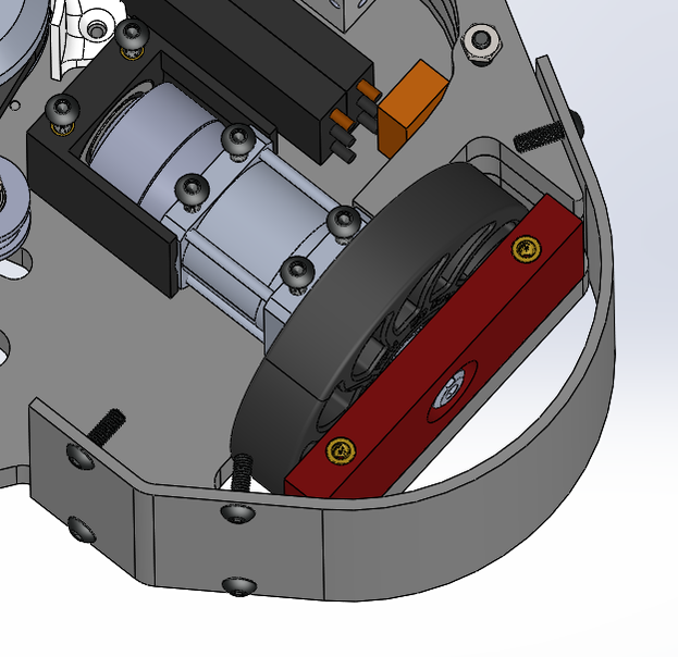
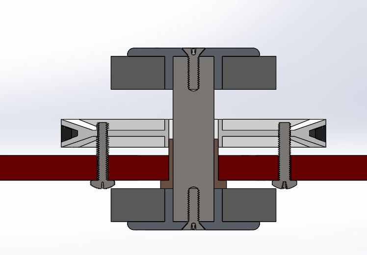
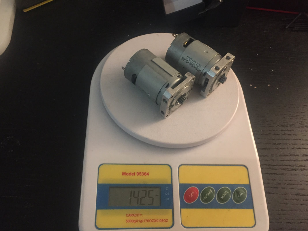
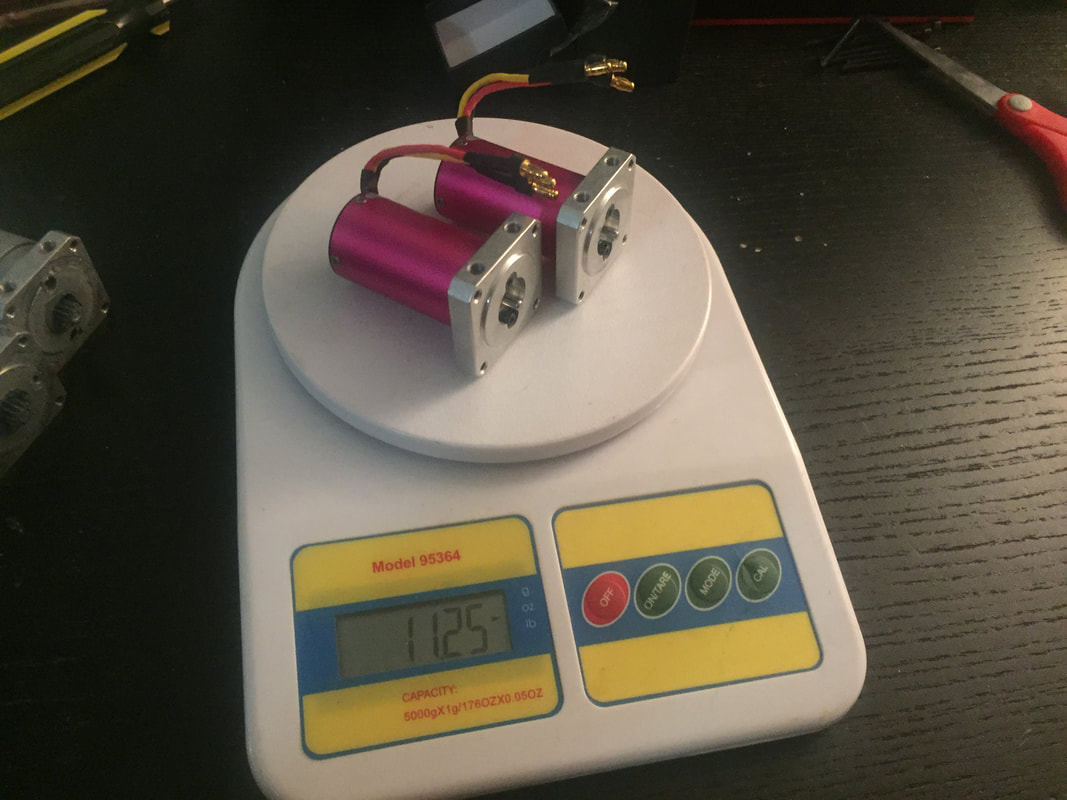
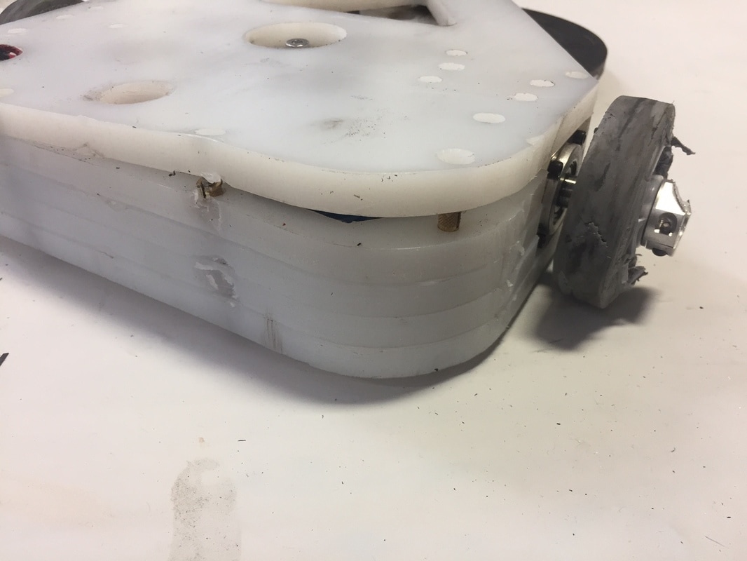
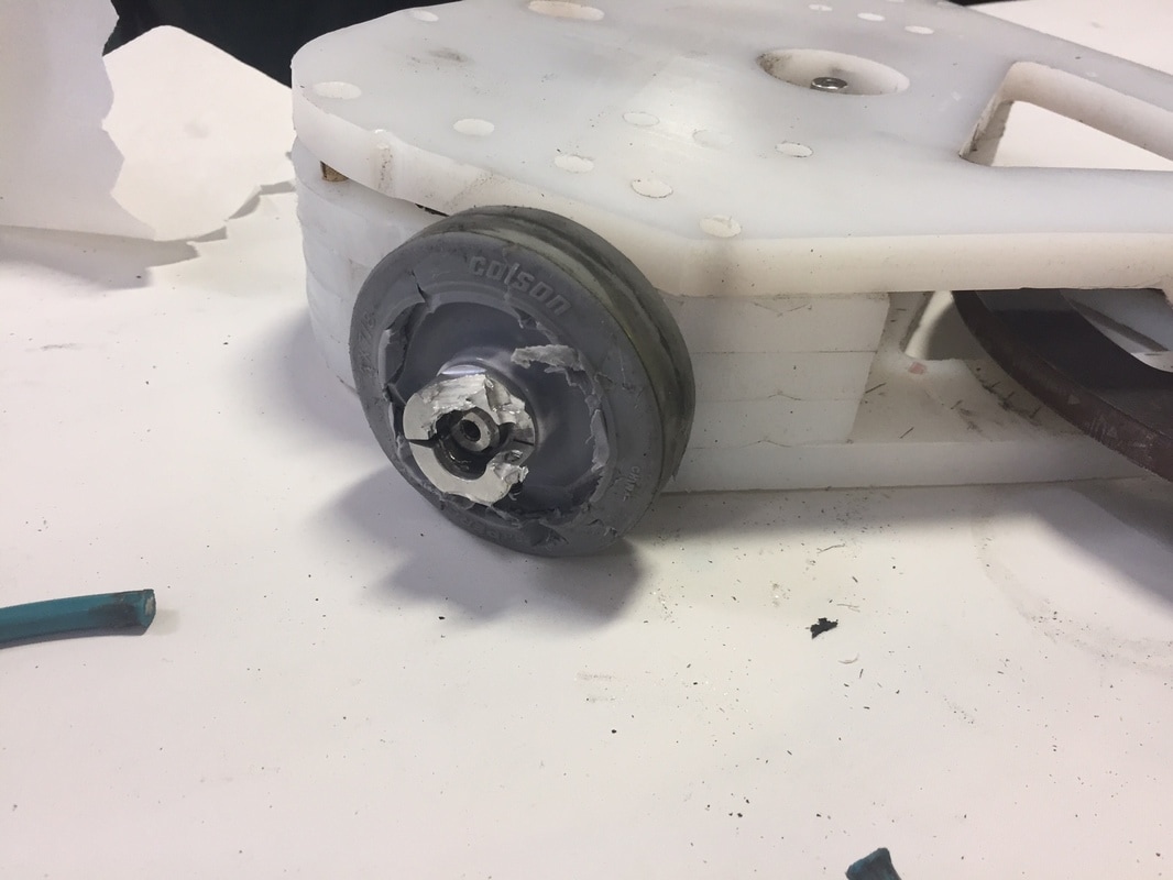
The drivetrain upgrades started with the motors. I switched to the Turnigy Aerodrive SK3 3536 1050kV motors. These are lower kV, higher power, higher torque motors that should help with the drive issues I'd been having. They also have a 5mm output shaft that should help keep the pinion gears more securely attached. The one downside to these motors however is the fact that as outrunners, the can of the motor is spinning at a very high rpm and can wear down anything touching it, including key electrical wires that would cause you to lose a fight. To protect these cans I developed some 3D printed wire guards that bolted onto the frame that surrounded the motors entirely. I wanted to continue supporting the rear of these motors like I had in previous versions of this design as I had had the problem of the motors coming loose of the gearbox in the past and wanted to make this drivetrain bulletproof. Because these are outrunners now, that meant adding bearings into the motor guards that slipped onto the nub on the end of the brushless motors to support them and avoid this issue. I took a similar approach to the output shaft of the gearboxes by adding a bearing into the wheel guards on the other side of the wheel. I haven't done this in the past due to weight, but with some of the recent upgrades, I made weight for some of these more experimental design elements. I'm interested to see how it works out. I should prevent the gear boxes from seeing big shock loads from being thrown around the arena, but might over-constrain the output shaft if it gets warped and might cause a different failure in practice.
The drivetrain upgrades started with the motors. I switched to the Turnigy Aerodrive SK3 3536 1050kV motors. These are lower kV, higher power, higher torque motors that should help with the drive issues I'd been having. They also have a 5mm output shaft that should help keep the pinion gears more securely attached. The one downside to these motors however is the fact that as outrunners, the can of the motor is spinning at a very high rpm and can wear down anything touching it, including key electrical wires that would cause you to lose a fight. To protect these cans I developed some 3D printed wire guards that bolted onto the frame that surrounded the motors entirely. I wanted to continue supporting the rear of these motors like I had in previous versions of this design as I had had the problem of the motors coming loose of the gearbox in the past and wanted to make this drivetrain bulletproof. Because these are outrunners now, that meant adding bearings into the motor guards that slipped onto the nub on the end of the brushless motors to support them and avoid this issue. I took a similar approach to the output shaft of the gearboxes by adding a bearing into the wheel guards on the other side of the wheel. I haven't done this in the past due to weight, but with some of the recent upgrades, I made weight for some of these more experimental design elements. I'm interested to see how it works out. I should prevent the gear boxes from seeing big shock loads from being thrown around the arena, but might over-constrain the output shaft if it gets warped and might cause a different failure in practice.
I'm really hopeful this version of Butcher will live up to its name. It was designed to be a big hitting bot that itself could take a few good hits, but recently it's had small issues that lead to big performance issues. We'll see how these upgrades hold up to the abuse of the competition at Smashbotz.
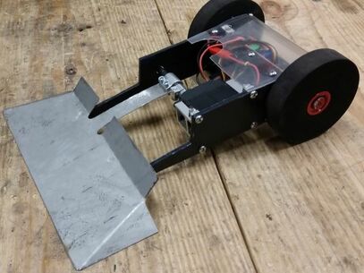
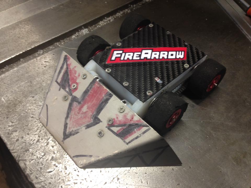
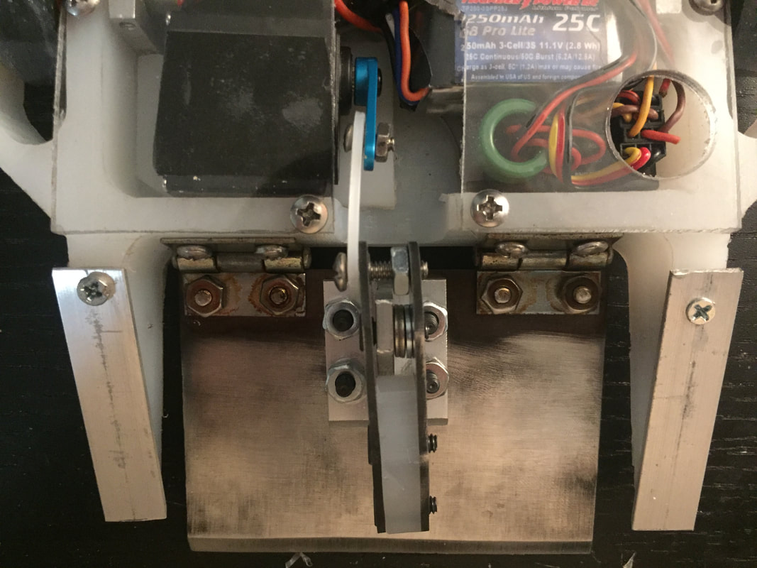
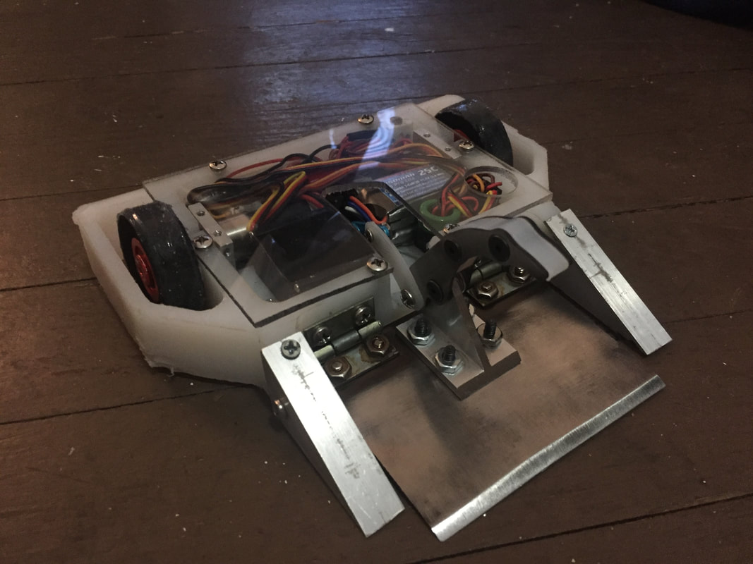
Drop Test 2.1
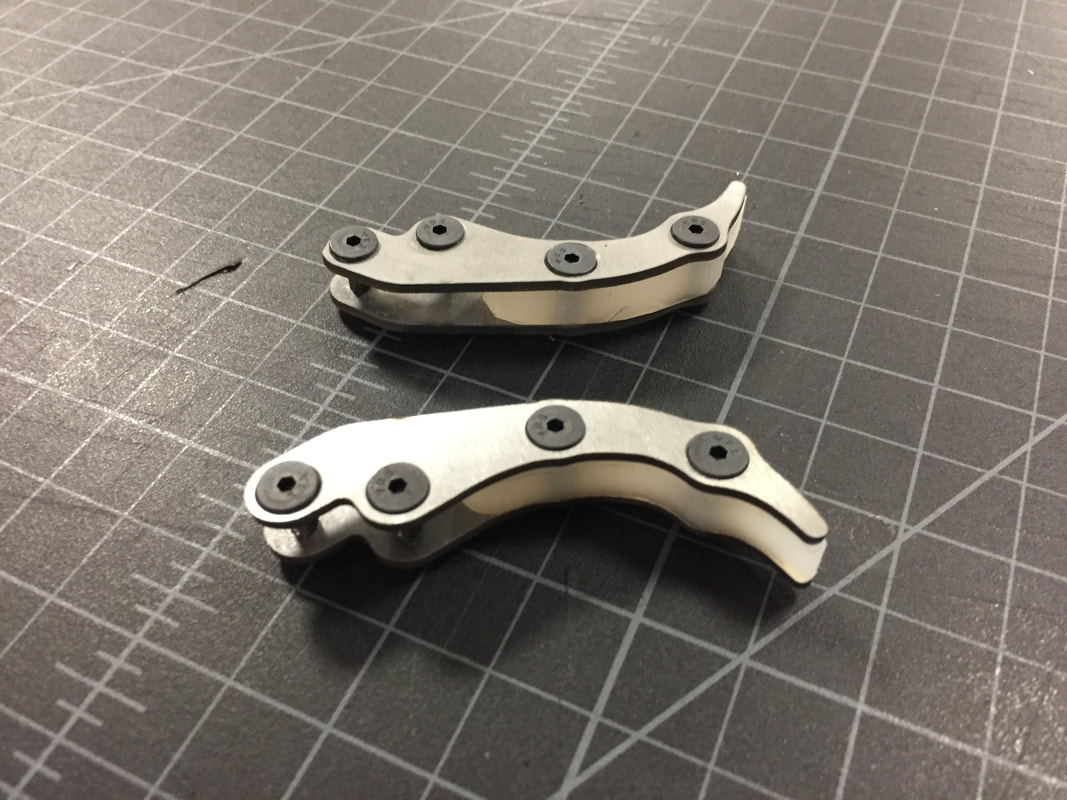
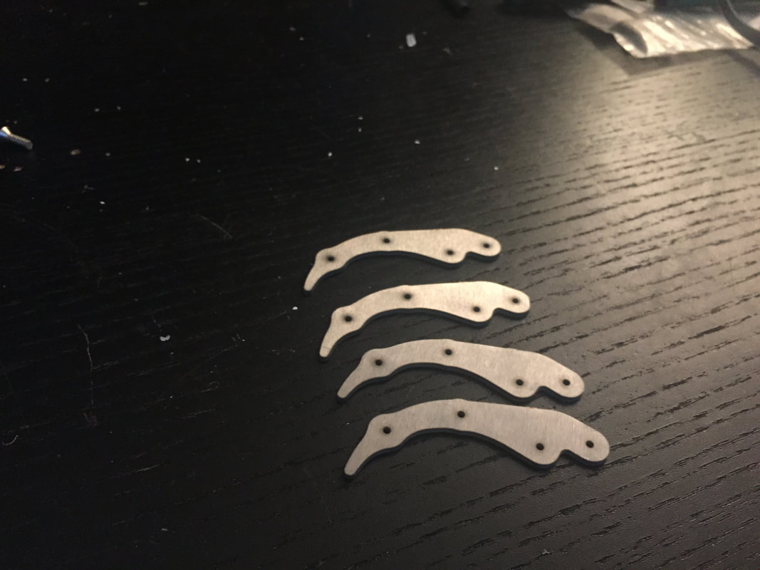
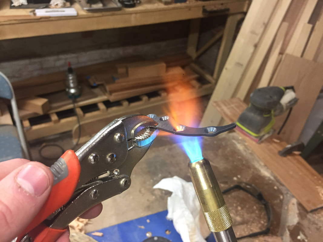
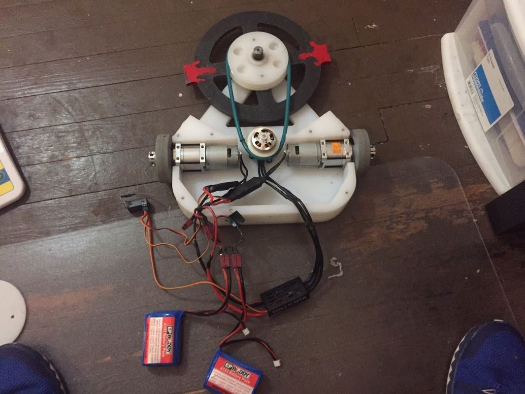
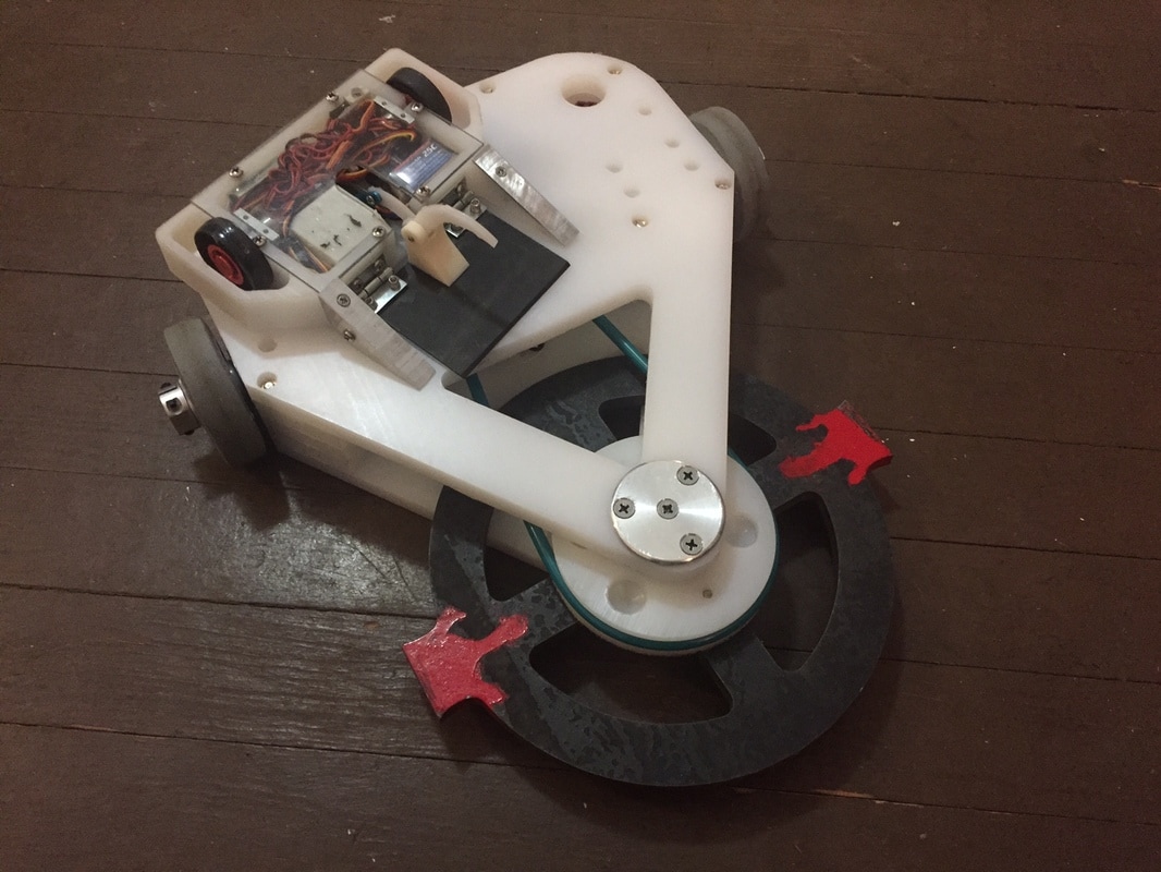
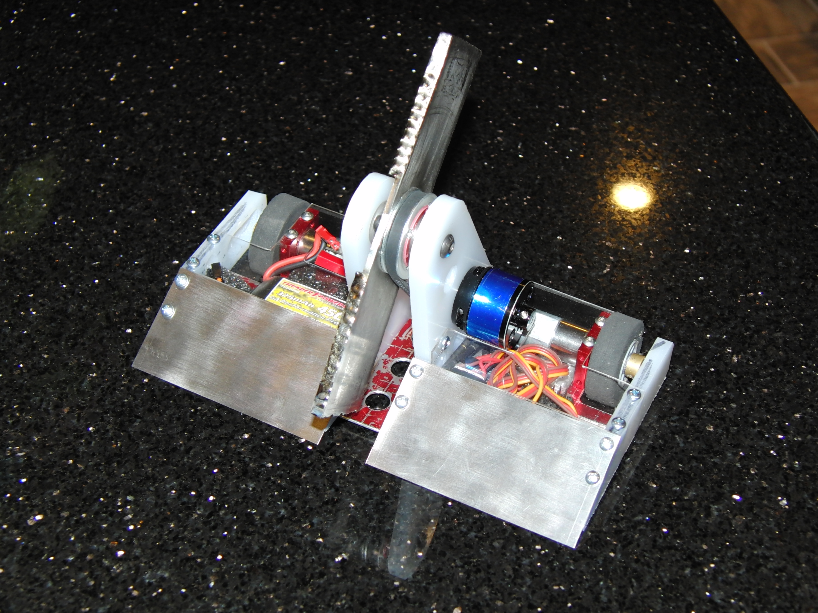
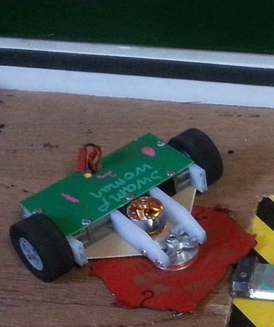
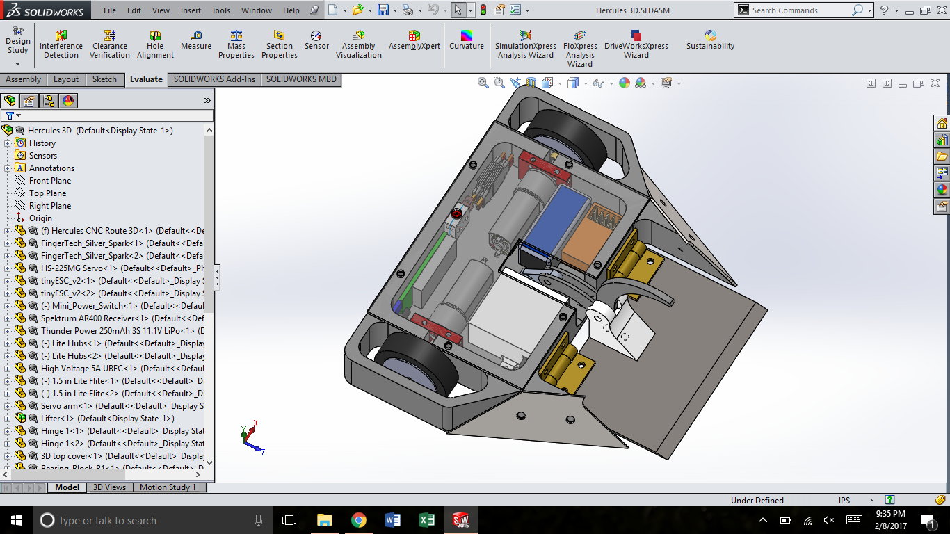
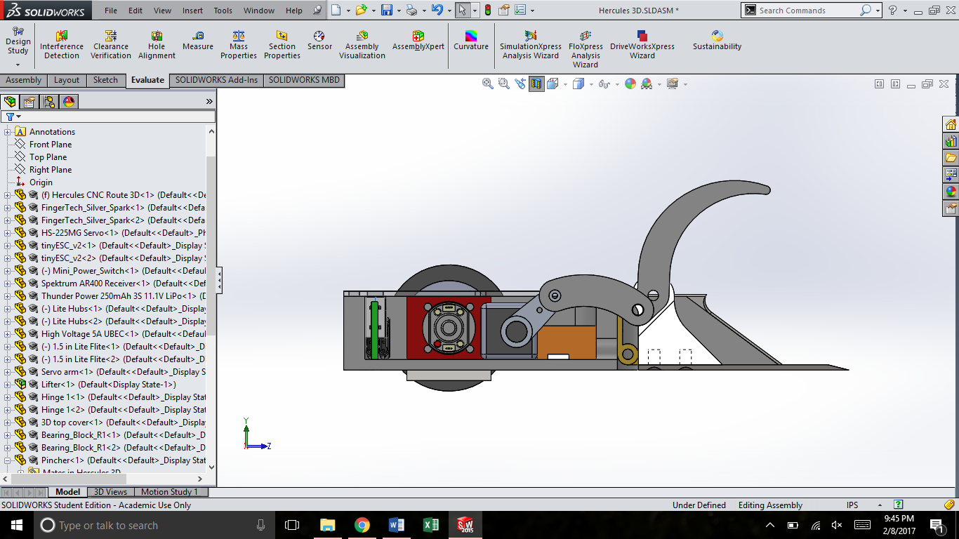
Part of the reason this post has been such a long time coming was because of Drop Test. Being by far the most complex combat robot I've designed to date, I expected there to be some growing pains and setbacks. But there's been even more than I expected. The core problem is that flippers in general are hard to build. They typically end up being relatively fragile because you have to fit so much in the same weight limit than other designs like spinners and wedges. The flipper mechanism takes up so much of the weight you don't have weight left over for other things like armor. In order to cut down the overall weight to make the design in the limit, I made some design compromises that came back to bite me since the previous update on this bot. I won't go into too much detail here, but one of the key issues was that in order to cut down the total weight of fasteners in the bot, I tried to make the frame all a single 3D printed piece. This ended up with me spending lots of money outsourcing the printing of the frame, only to have issues with is since it wasn't optimized for 3D printing and having to scrap the entire frame multiple times due to small errors.
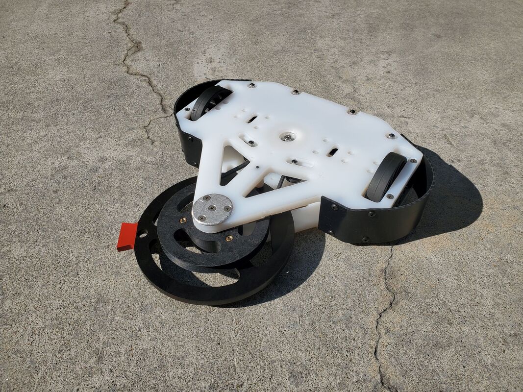
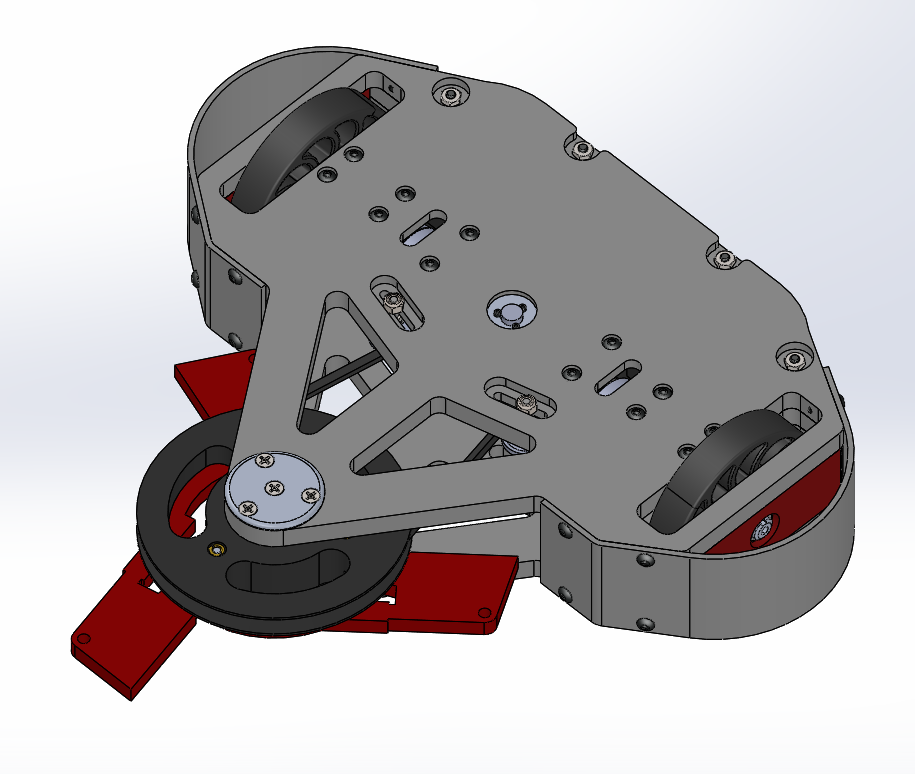
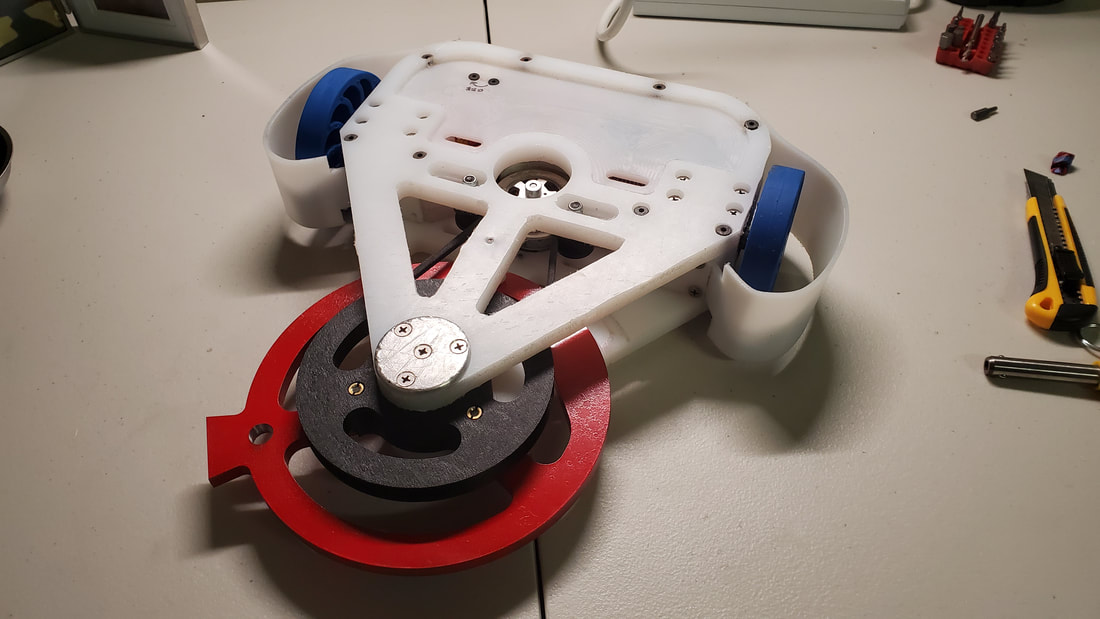
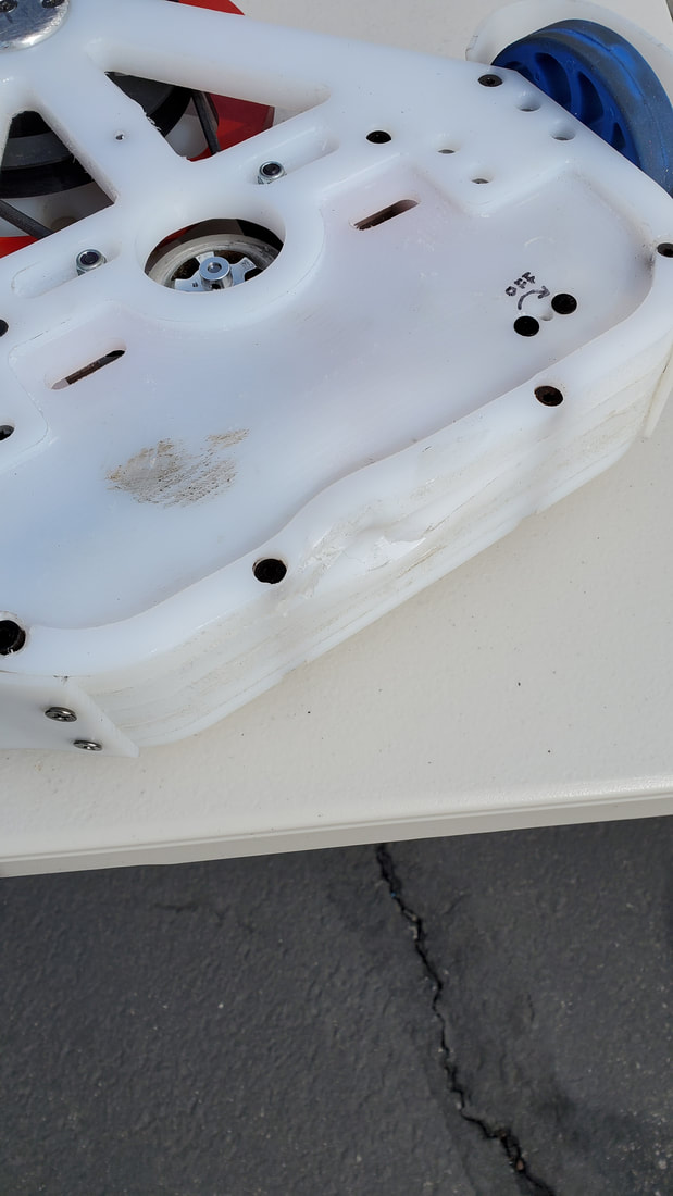
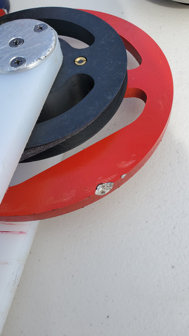
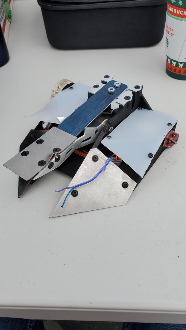
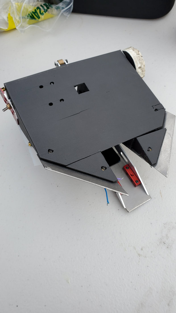
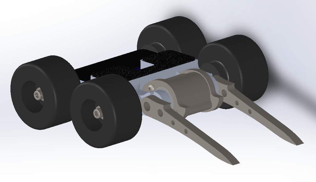
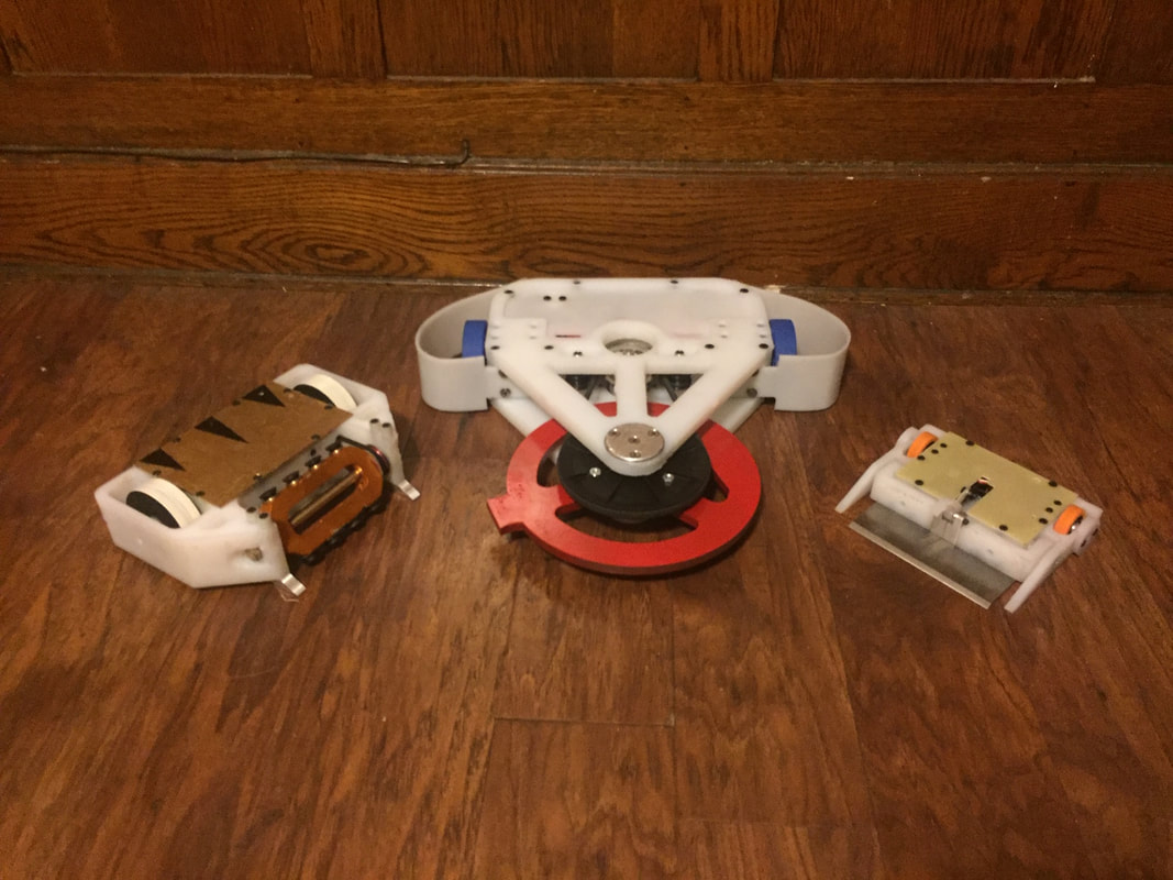
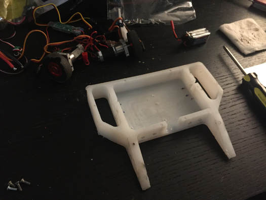
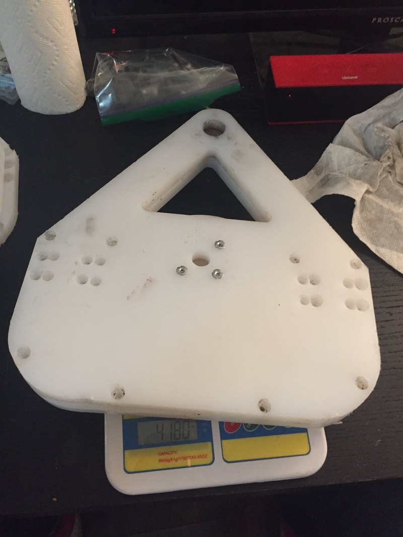
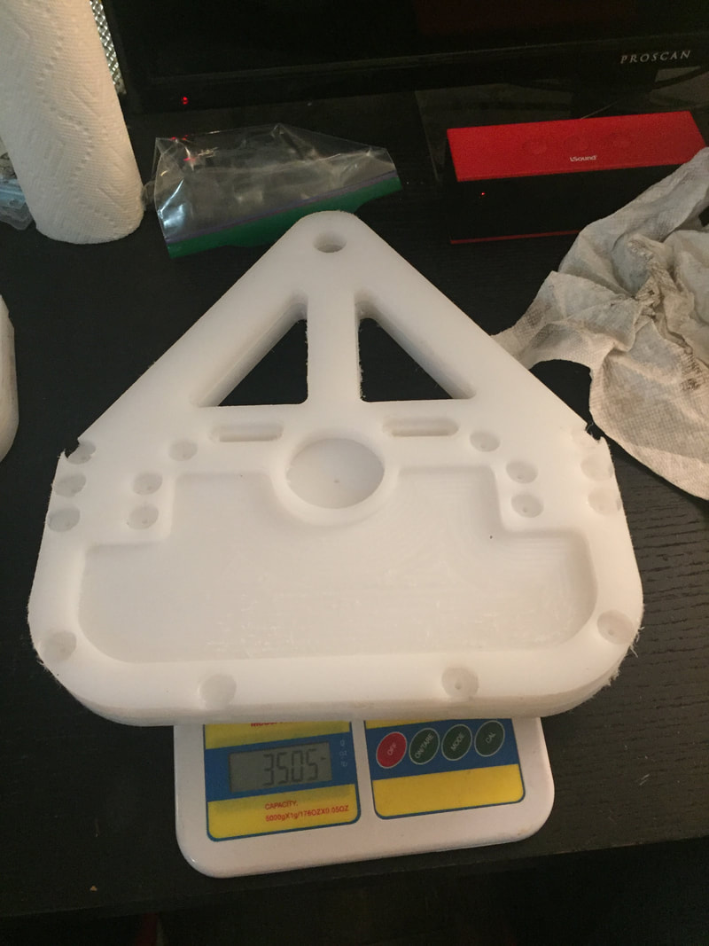
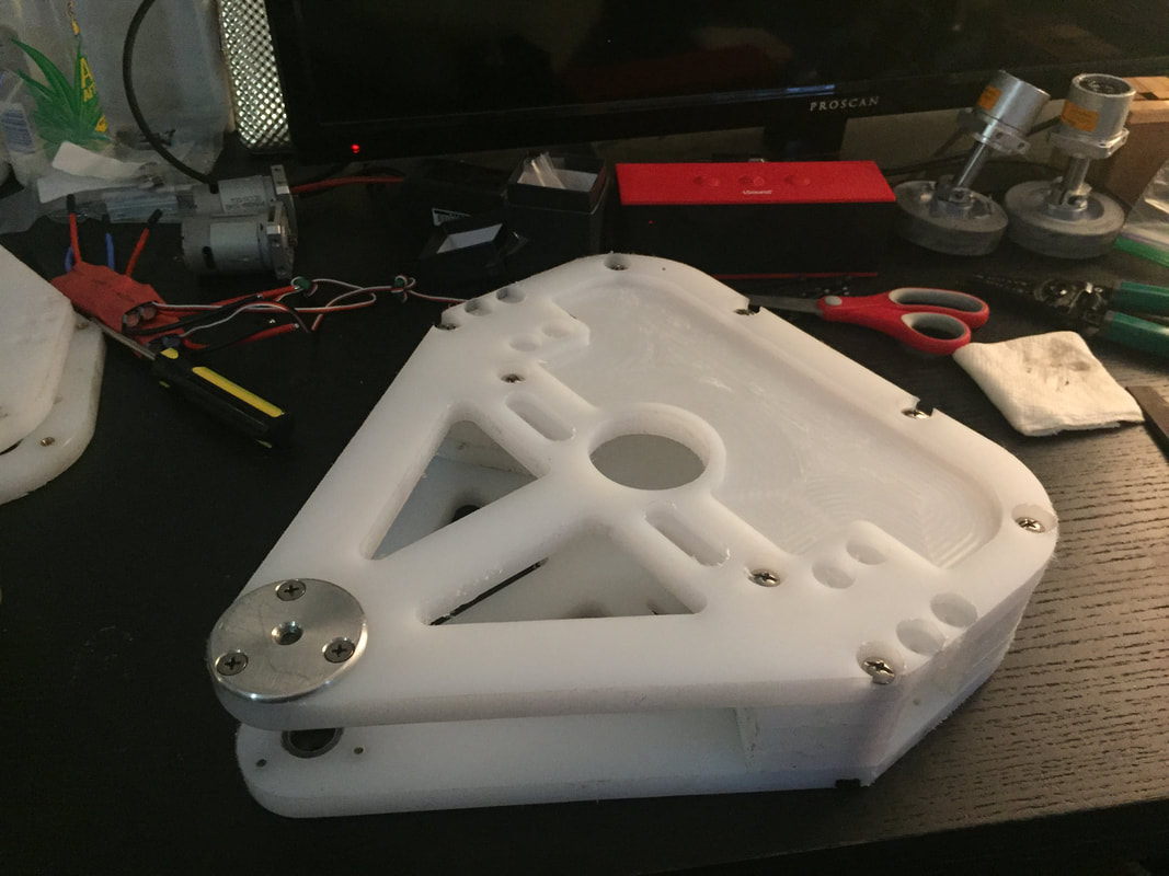
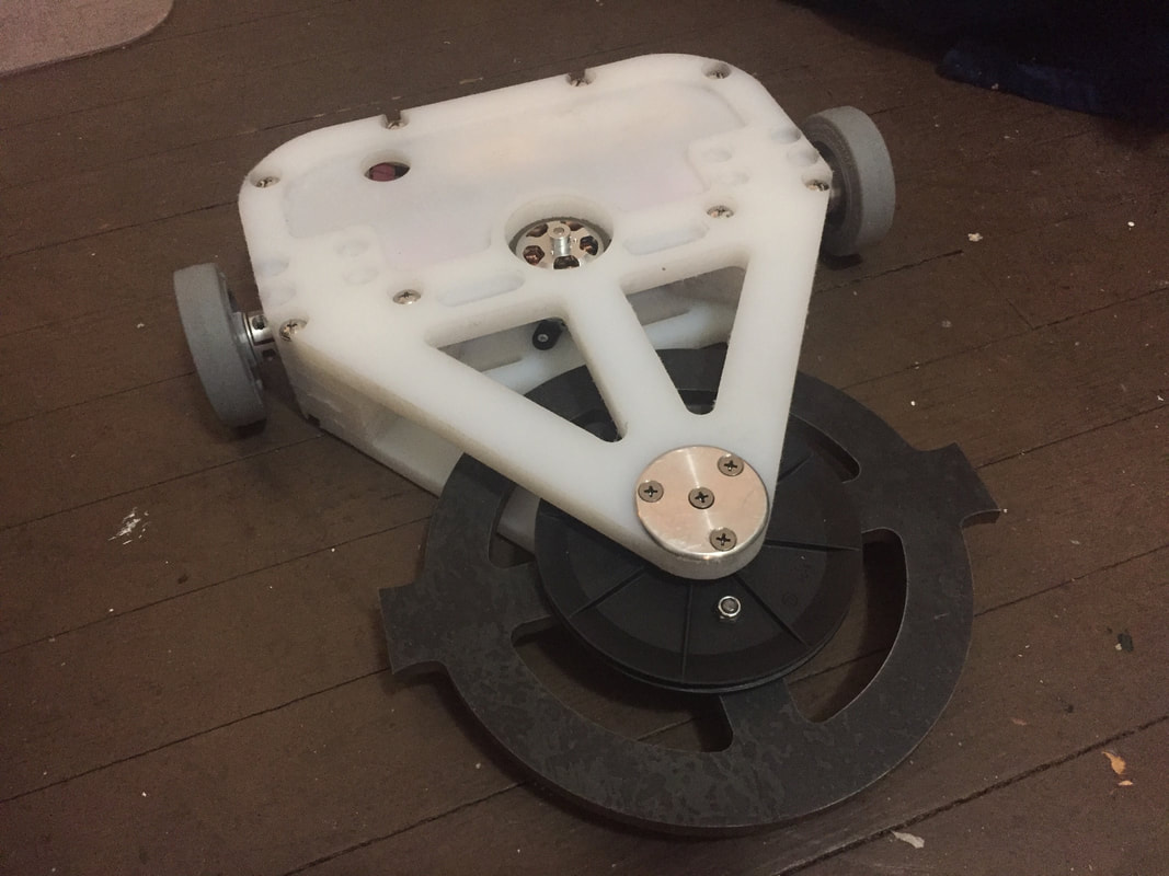
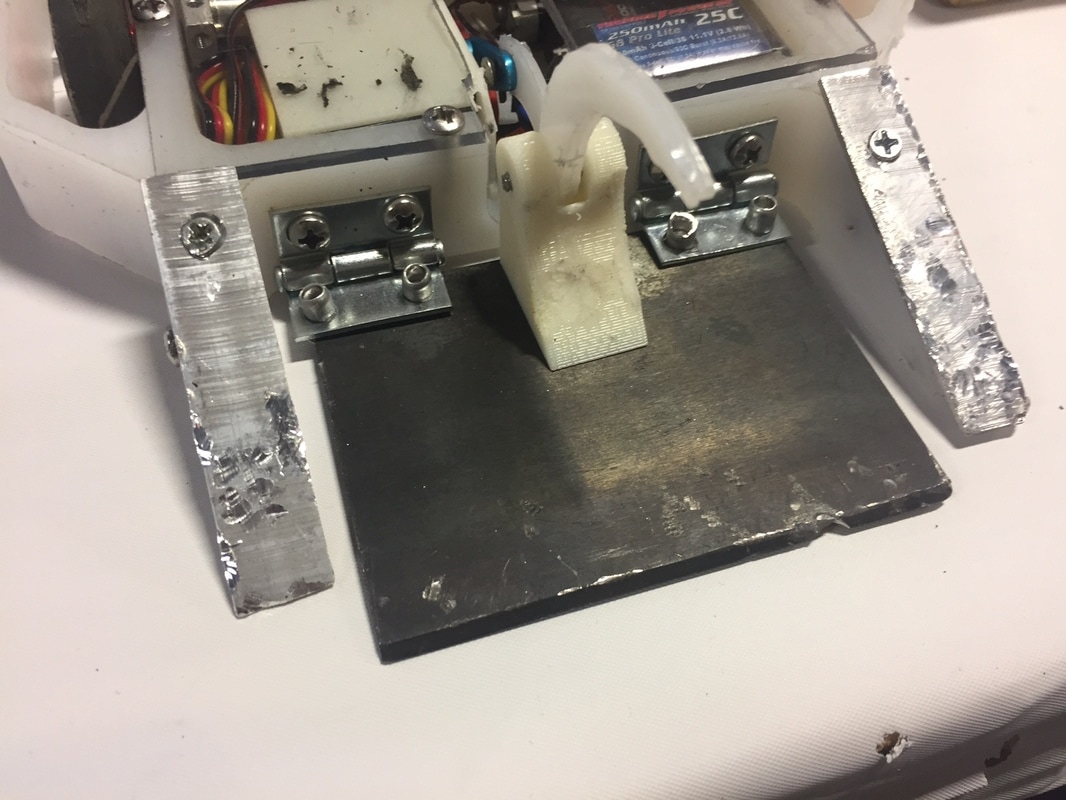
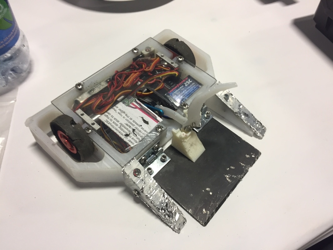
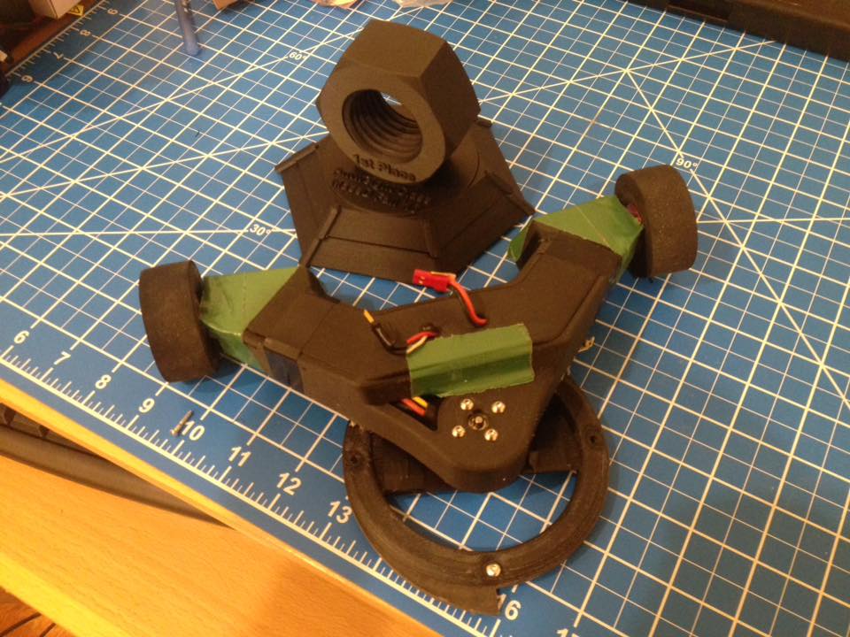
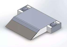
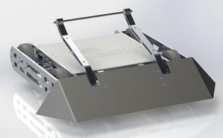
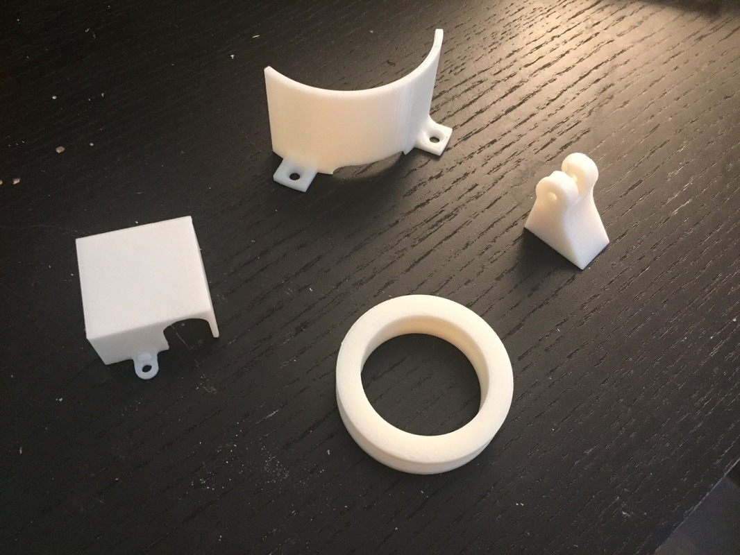
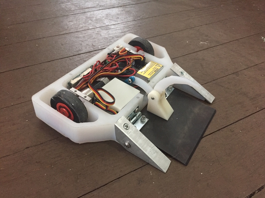
I have since bought my own 3D printer and re designed Drop Test to be more printable. You can see a PLA mockup of the new design below that shows the 4 independent frame rails that are much more printable, even without supports, and make assembly and maintenance way easier.
I have since bought my own 3D printer and re designed Drop Test to be more printable. You can see a PLA mockup of the new design below that shows the 4 independent frame rails that are much more printable, even without supports, and make assembly and maintenance way easier.
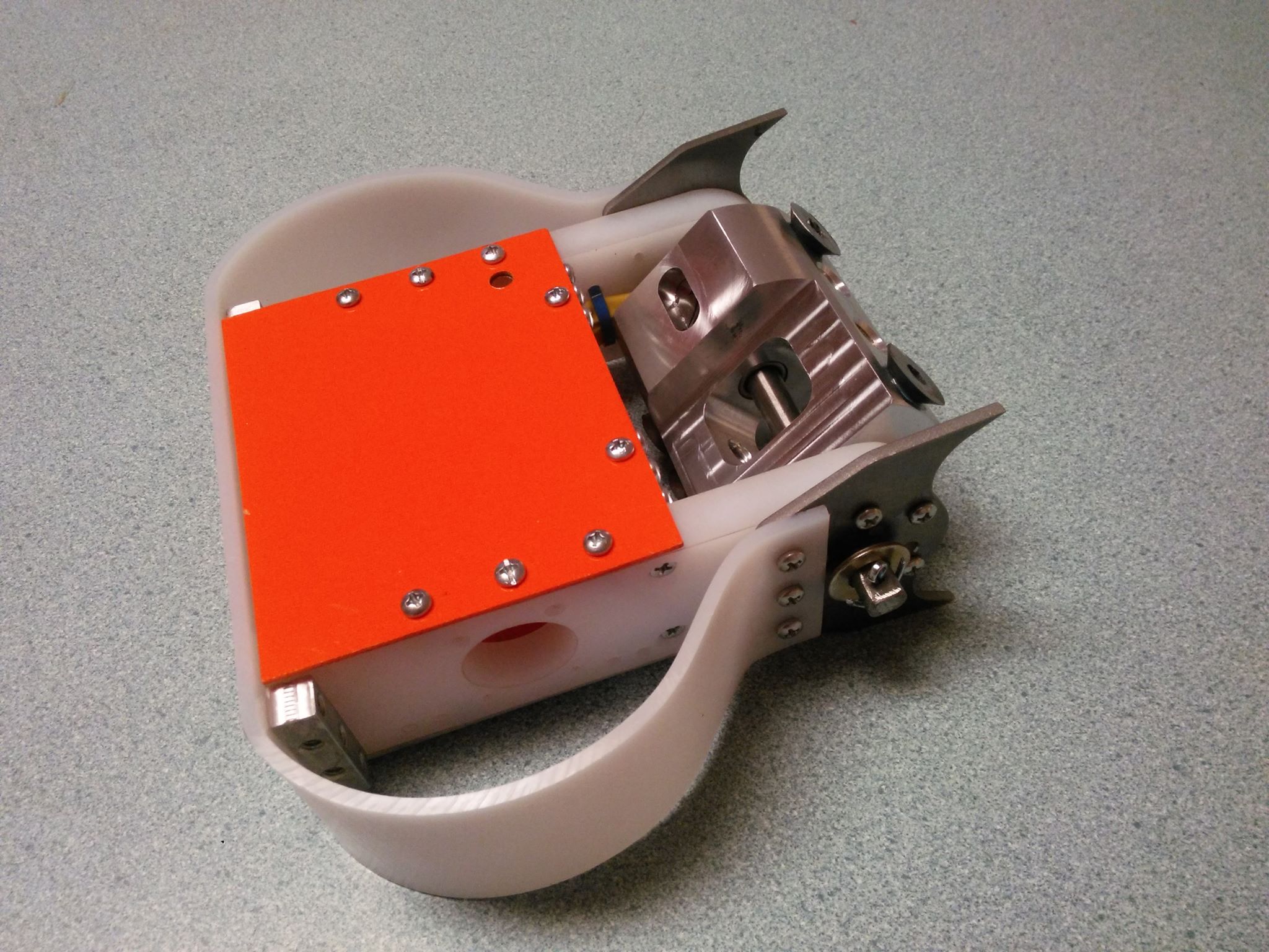
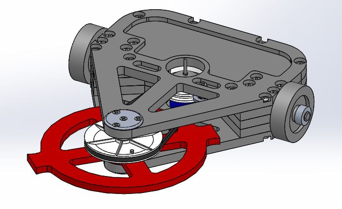
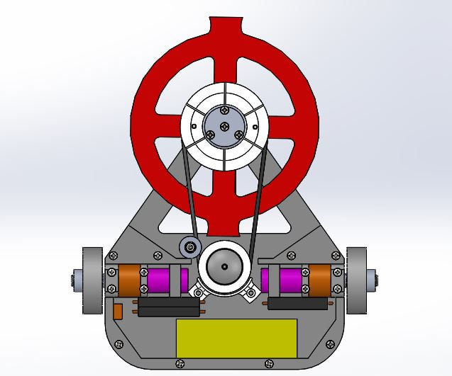
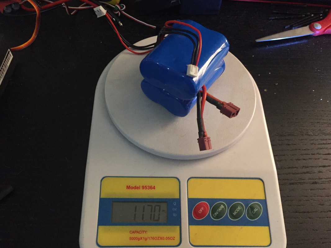
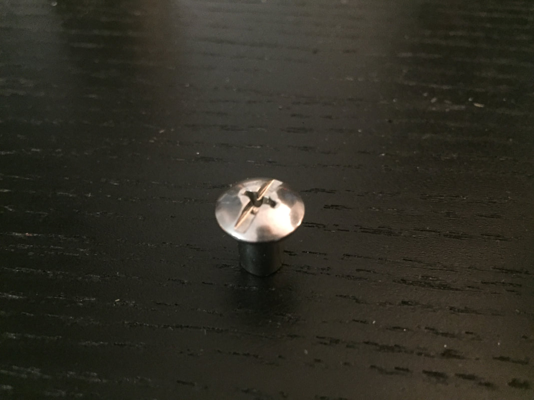
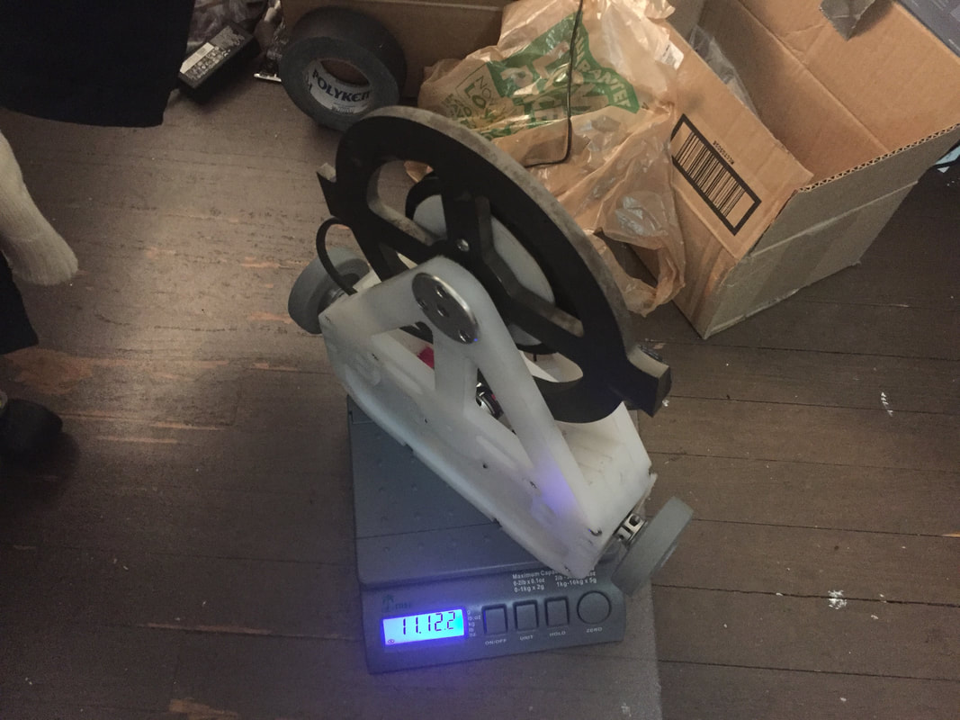
An issue with these changes though was weight. Like I said, I had designed the unibody to eliminate fasteners, but this design, though it had it's own advantages, had about twice the number of fasteners. This meant both the screws that hold everything together and the brass heat set inserts in the frame. And at such a small weight limit, that added up quickly. So weight had to be cut elsewhere.
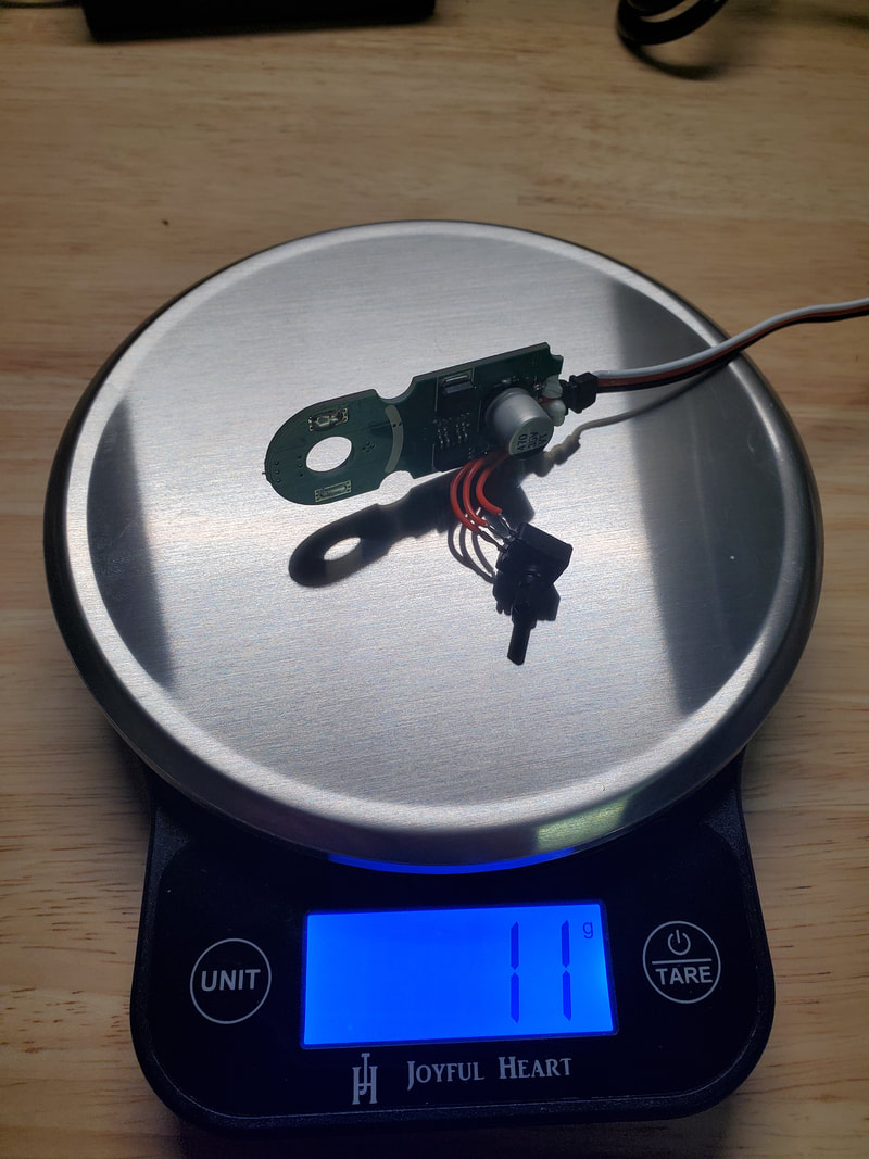 | 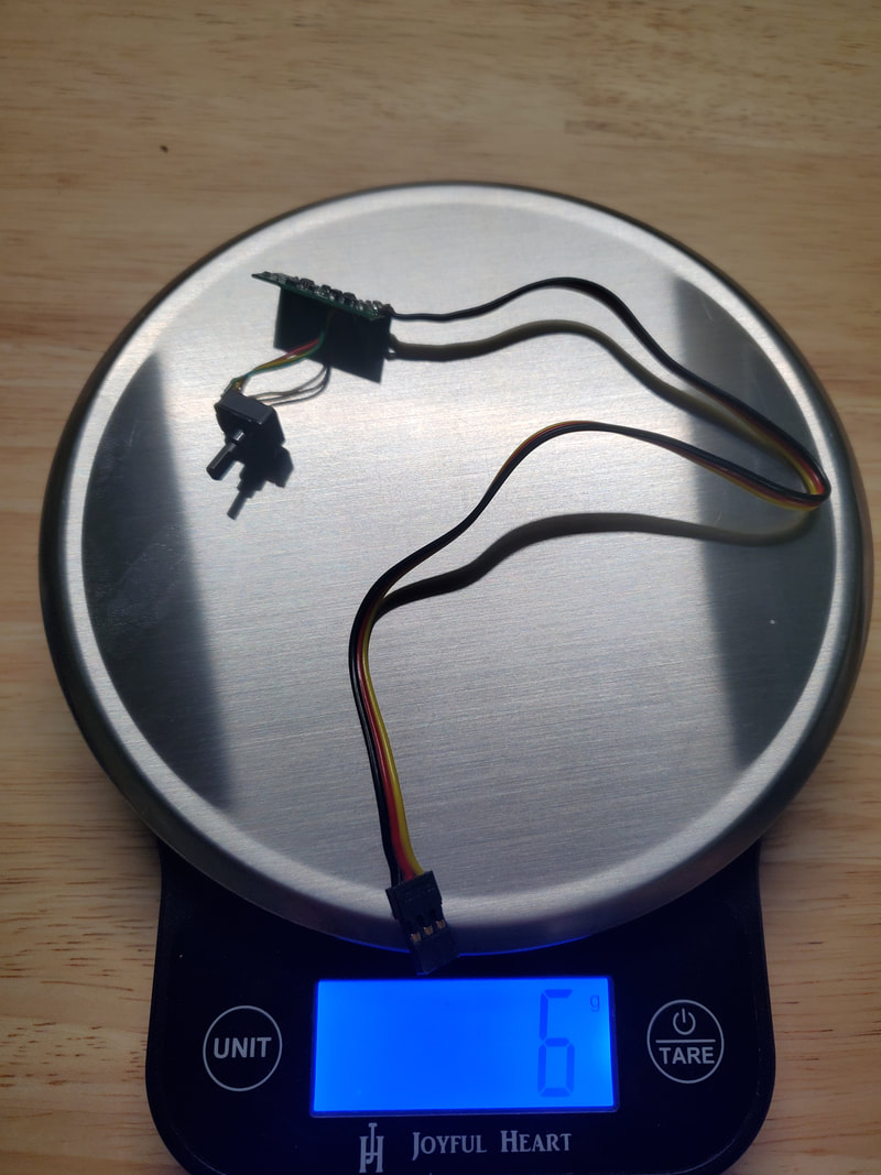 | 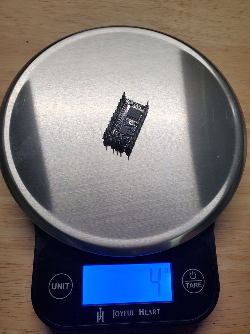 |
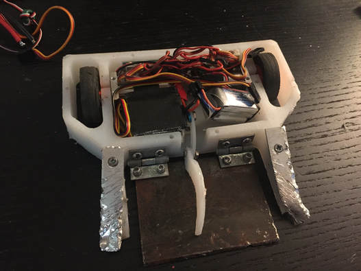
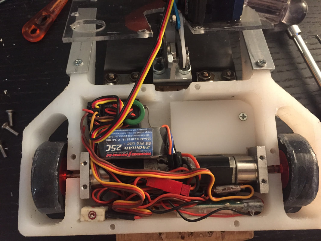
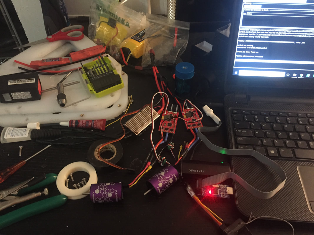
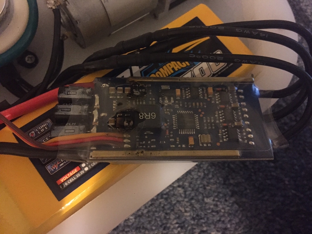
I had originally planned on using the PCB from a large servo I disassembled to drive the motor for the flipper system, but at 11g and fairly large, it definitely wasn't ideal for the re-design. I found a smaller servo board from a slightly smaller servo, but it was slightly under the current rating of the motor I was trying to use, and I didn't love the fact that I had to buy the whole servo only to waste most of it to steal this board for my own use. That's when I can across the Pololu Baby Orangutan, a "robot controller" that integrates the same microcontroller as an Arduino Nano into a smaller package with built in H Bridges for motor control. At 1.5g without the headers, this seemed perfect for my application. I could program it so serve as a servo board with a trigger input from the receiver to be able to run the firing and reset sequences without me having to worry about firing and resetting while I'm driving. I forged ahead with this as my selection, completely disregarding the fact that I'd never used this system before and would have to learn to interface with it and source/create code for the servo feedback system to drive the trigger mechanism to my desired positions and timing sequences.
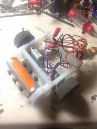
As you might be able to tell from my bitter retrospective tone, this didn't turn out that well for me. This project throughout its lifetime has been the most complex combat robot I've made to date. And as such, requires much more focused attention to detail than any of my other projects. Given that combat robotics is just a fun hobby for me, I don't always put the same effort into details as I would for my job. I also don't spend nearly as much time on it as I would for more professional projects, maybe a few hours a week. All of this meant two things:
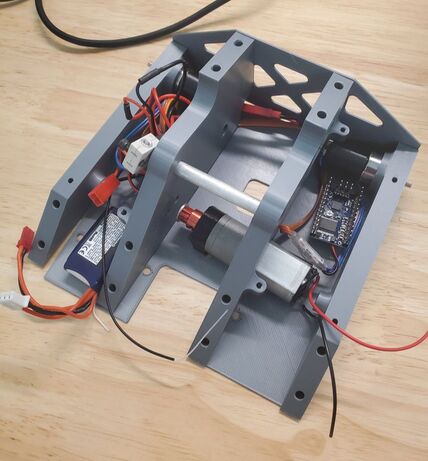
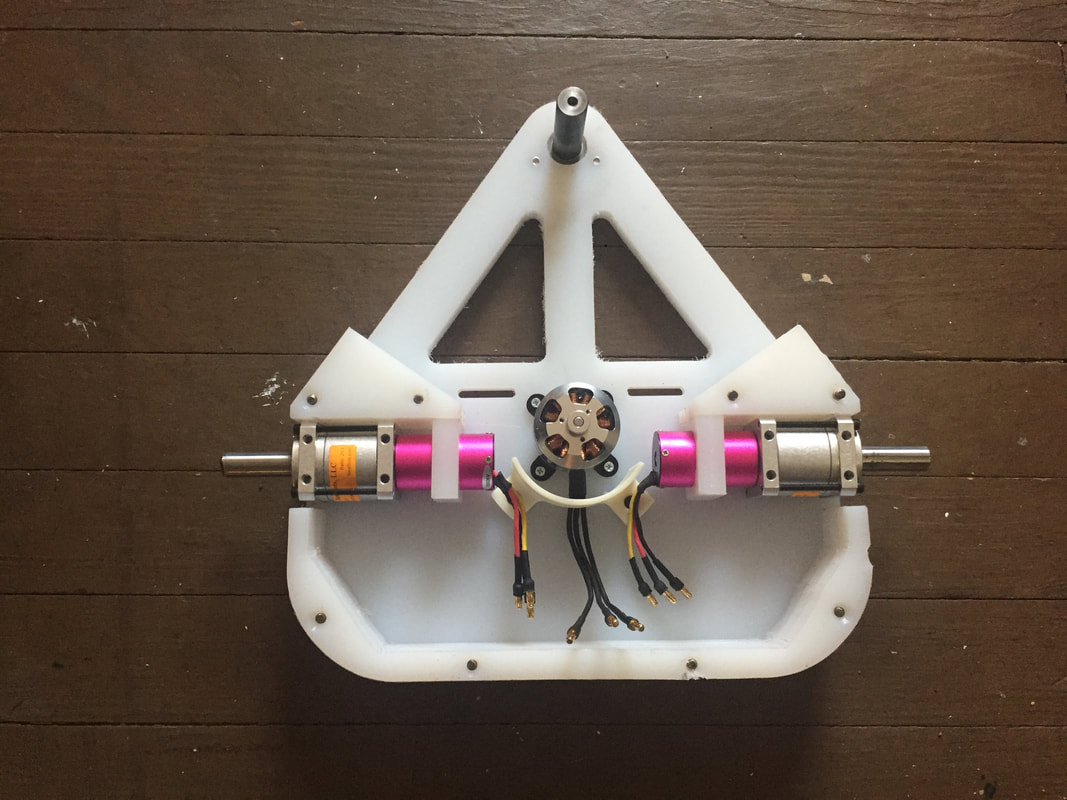
All that being said, I did make some good progress on this design, it just didn't come to completion. The biggest win in my opinion is the fact that I got the motor driver working as intended. I was unable to get a good video of it as the belt that connects the motor to the trigger was too loose and couldn't handle the loads required. As such, the video below shows the auto firing of the mechanism by way of my exciting the triggering pin on the controller by hand to simulate the PWM input from my transmitter. You can hear the belt skipping in the video, but it does work.
As you might be able to tell from my bitter retrospective tone, this didn't turn out that well for me. This project throughout its lifetime has been the most complex combat robot I've made to date. And as such, requires much more focused attention to detail than any of my other projects. Given that combat robotics is just a fun hobby for me, I don't always put the same effort into details as I would for my job. I also don't spend nearly as much time on it as I would for more professional projects, maybe a few hours a week. All of this meant two things:
- This build still had a lot of small oversights in the design mechanically that had to be fixed
- This project took a lot longer than I expected. Even more so because of point 1
All that being said, I did make some good progress on this design, it just didn't come to completion. The biggest win in my opinion is the fact that I got the motor driver working as intended. I was unable to get a good video of it as the belt that connects the motor to the trigger was too loose and couldn't handle the loads required. As such, the video below shows the auto firing of the mechanism by way of my exciting the triggering pin on the controller by hand to simulate the PWM input from my transmitter. You can hear the belt skipping in the video, but it does work.
This isn't the update on Drop Test I was hoping to give, and it likely wasn't the one you were hoping to read. But I promise there will be more updates in the future with better news. I won't give up on this, at this point, it's personal.

 RSS Feed
