This post will likely be the last non-combat robotics related post on here for a while. I have finished up my master's degree that prevented me from having free time to work on combat robotics related things. I feel like I owe the readers of this blog an explanation while at the same time providing a look into some of the more real-world applications to the same design principles that I use in combat robotics.
Introduction
My thesis was part of a larger project in the Case Western Biologically Inspired Robotics Laboratory that has been developing a lower extremity exoskeleton for people with spinal cord injuries in order to help them to rehabilitate to walk again. My specific project focused on the design of the actuators that move each of the major lower body joints, the hips, knees, and ankles. These actuators must provide the proper torque and speed outputs to match the typical walking cycle needs while being as small and light weight as possible. This is accomplished through the use of a DC electric motor, a transmission, and an electrically operated brake, all in one package.
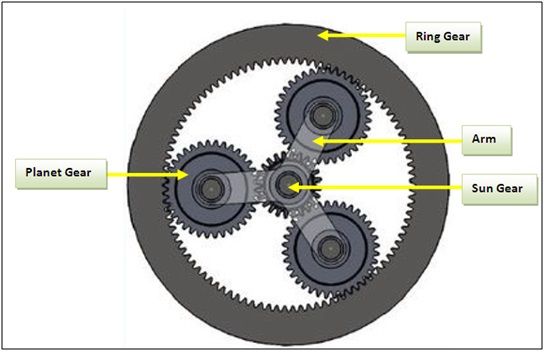
The unique design feature of the actuator that I designed is it's use of a planetary gearbox as a source of transmission. Many of the exoskeleton actuators that are being used in both commercial and research applications at this time are using harmonic drives as a transmission. Harmonic drives are a very special type of transmission, designed specifically for high precision robotic applications.
The unique design feature of the actuator that I designed is it's use of a planetary gearbox as a source of transmission. Many of the exoskeleton actuators that are being used in both commercial and research applications at this time are using harmonic drives as a transmission. Harmonic drives are a very special type of transmission, designed specifically for high precision robotic applications.
Harmonic drives work on a very unique principle called strain wave gearing. You can see a more detailed explanation of the inner workings of a harmonic drive in the video above. Due to the nature of the design, harmonic drives provide very high gear reductions in a very small space with virtually no backlash. This is of great use to many robotic applications where size and precision are key constraints on the system.
Harmonic drives do have their drawbacks as well though. Because the two splines are in constant rolling contact with one another and have to be strained to do so, harmonic drives are very high friction systems. This means it takes a considerable force to start them rotating, and once up to speed, a considerable amount of the energy put into the system is lost due to friction. This is less of an issue in applications where harmonic drives are typically used such as robotic arms in industrial settings because they are connected to the power grid and energy usage and weight are less important than size and precision. Because the exoskeleton is a mobile robot, these priorities shift in favor of a more efficient system that can more efficiently convert the electrical power in the batteries into mechanical power. This is where the planetary gearbox comes in. Planetary gearboxes are significantly higher mechanical efficiency systems than harmonic drives that can more efficiently use the stored energy at the cost of a small drop in precision due to backlash of the gears.
Harmonic drives do have their drawbacks as well though. Because the two splines are in constant rolling contact with one another and have to be strained to do so, harmonic drives are very high friction systems. This means it takes a considerable force to start them rotating, and once up to speed, a considerable amount of the energy put into the system is lost due to friction. This is less of an issue in applications where harmonic drives are typically used such as robotic arms in industrial settings because they are connected to the power grid and energy usage and weight are less important than size and precision. Because the exoskeleton is a mobile robot, these priorities shift in favor of a more efficient system that can more efficiently convert the electrical power in the batteries into mechanical power. This is where the planetary gearbox comes in. Planetary gearboxes are significantly higher mechanical efficiency systems than harmonic drives that can more efficiently use the stored energy at the cost of a small drop in precision due to backlash of the gears.
Calculations
Because this is a blog post and not my actual thesis, I will keep this section relatively short and give a general overview of some of the math that went into the design of this project. The design requirements of the actuator come from the physical requirements of the average human during a normal walking cycle. There are multiple papers written just on this, but through my research I found that in order to design an actuator that would work at either the hips or the knees, it would need roughly 50N-m of torque at 150 deg/s. The reason the ankles were excluded from this design is that their torque needs are roughly twice that of the hips and knees, but the same design principles apply.
From there the motor was selected. The main constraints on the motor in this case are the voltage, current, and size of the motor. The output voltage and peak current supply of the controls system had already been set at this point in the project and needed to be designed around. The motor would need to be as flat as possible while still providing enough torque. This is so the actuator doesn't stick out too far from the user during use. A hubless, brushless, DC motor was selected that fit the requirements with 1 Nm peak of torque.
With the motor settled, the gear ratio needed to be determined. In order to get 50 Nm peak out of the actuator, the transmission had to be 50:1. This actually isn't as simple as it sounds due to the nature of planetary gear systems. I will leave out most of the calculations in order to keep this section brief, but more information can be found here. I will explain that it is very difficult to achieve a single stage planetary reduction of more than 10:1, so I knew this would have to be a multi-stage transmission. I settled on using a set of spur gears to achieve an initial 2:1 reduction and two 5:1 planetary stages for a total of 50:1
In order to ensure the gear teeth could handle the expected load of the actuator, the Lewis gear strength equation was used. Again, I don't want to go into too much detail on this, but the idea behind the equation is to estimate the stress on the gear teeth by treating them as cantilever beams with a static load on the end. The stress on each tooth is based on the pitch of the gear, the width of the gear face, the number of teeth in the gear, and the load on the tooth. As the teeth get smaller or the load increases, so does the stress on the gear teeth.
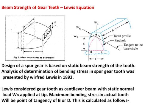
For planetary gear sets, the typical shape is long and skinny, such as in a drill gearbox. This is done in order to save space and weight by making the gears smaller and thicker. For this application however, the main size constraint is how thick the actuator is. So, the typical shape would not work. By manipulating the Lewis equation I found a solution that was able to handle the expected loads while being thin as possible by increasing the overall diameter of the ring gears.
Finally, the efficiency needed to be calculated. Like I mentioned in the intro, the main consideration driving the use of a planetary system over a comparable harmonic drive is the efficiency. This was done based off of the work of a few scientific papers that I found that used the known mechanical losses of spur gears and transformed them into overall mechanical efficiencies of a planetary set up. I don't have a good link for this one that is publicly accessible as most were higher level research papers, but the idea is that there has been a lot of research into the efficiency of various sizes of mating spur gears. By treating the two sets of meshing gears (sun to planet, and planet to ring) as two sets of spur gears you can generate a basic efficiency. Based off of which gear is your input and which is your output, you can estimate the overall efficiency of the stage. This efficiency calculation was done for the spur gear stage and the two planetary stages to combine for a theoretical efficiency of around 95%.
Finally, the efficiency needed to be calculated. Like I mentioned in the intro, the main consideration driving the use of a planetary system over a comparable harmonic drive is the efficiency. This was done based off of the work of a few scientific papers that I found that used the known mechanical losses of spur gears and transformed them into overall mechanical efficiencies of a planetary set up. I don't have a good link for this one that is publicly accessible as most were higher level research papers, but the idea is that there has been a lot of research into the efficiency of various sizes of mating spur gears. By treating the two sets of meshing gears (sun to planet, and planet to ring) as two sets of spur gears you can generate a basic efficiency. Based off of which gear is your input and which is your output, you can estimate the overall efficiency of the stage. This efficiency calculation was done for the spur gear stage and the two planetary stages to combine for a theoretical efficiency of around 95%.
As with most engineering design processes, the majority of the calculations were done in an iterative process using a large spreadsheet to repeatedly perform these calculations to optimize the system. The gears that were selected were all set to be modified from off the shelf parts to incorporate into the gearbox. Each set of gears was checked that it had the proper gear ratio, an adequate factor of safety from the gear teeth yielding, and an acceptably high theretical efficiency.
CAD Design
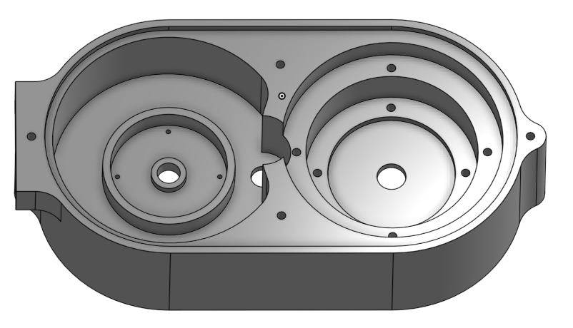
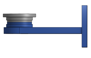
This section will mostly be pictures with me highlighting a few key design features that are helpful to making the actuator as compact as possible. First, a look at the overall design:
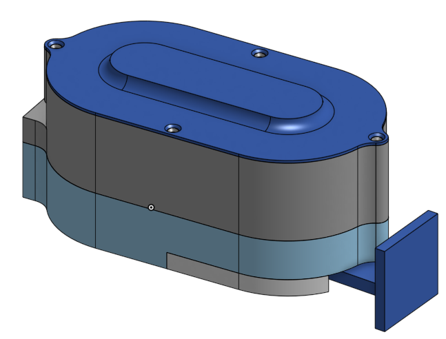 | 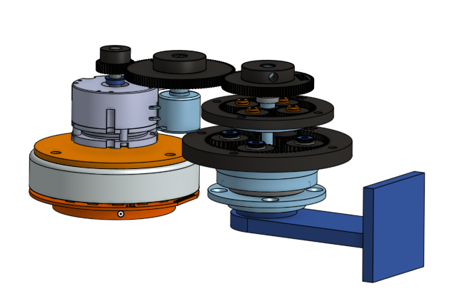 |
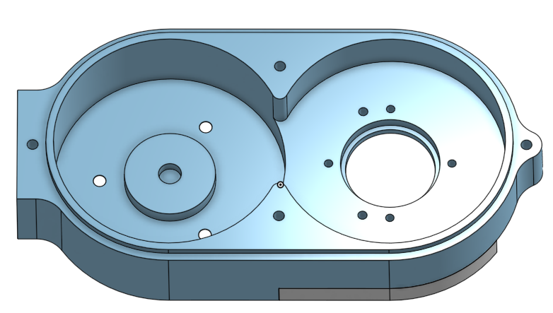
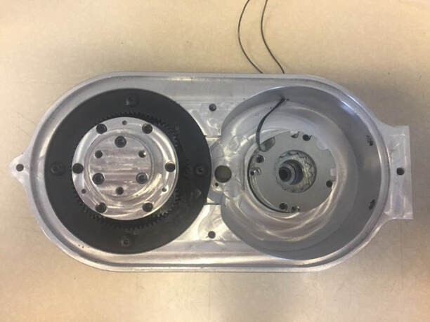
On the left is the overall final actuator design and on the right is a view of the internal components. The actuator is designed to be rigidly mounted on one end with an arm that rotates to provide the actuation for the specific joint. Inside you can see the main components: the frameless, brushless, DC motor with a custom hub in the bottom left; the normally closed, electrically operated brake above that; and the sets of gears that act as the transmission to the output arm on the bottom right. You can also see the two main sensors that provide feedback to the controls system: a potentiometer on the second spur gear, and a torque sensor placed on the output of the transmission before the output arm. These two sensors provide positional and torsional feedback respectively to the controls system.
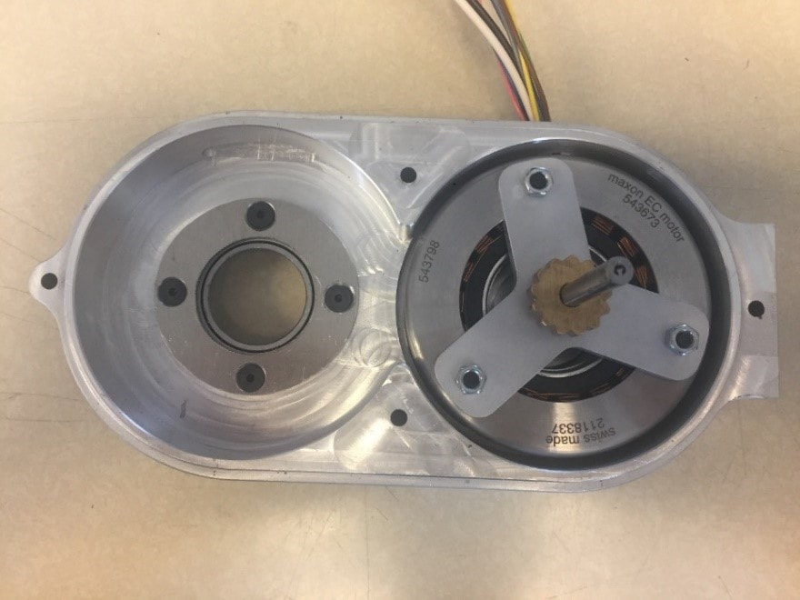
The housings are designed in a way to ensure that all of the parts align concentrically to one another. The two housings each have a lap joint around the perimeter to align the housings to eachother (see below). All of the key features of the housings that align the components are designed so that they can be machined in a single operation on a CNC mill. This setup makes it significantly easier to ensure that all of the parts align with one another to prevent binding issues.
The housings are designed in a way to ensure that all of the parts align concentrically to one another. The two housings each have a lap joint around the perimeter to align the housings to eachother (see below). All of the key features of the housings that align the components are designed so that they can be machined in a single operation on a CNC mill. This setup makes it significantly easier to ensure that all of the parts align with one another to prevent binding issues.
 |  |
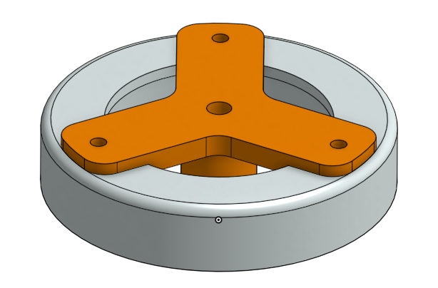
Another key feature of this design is the use of a cross roller bearing on the output arm. This bearing takes both axial and radial loads due to its unique design. The output arm is designed in a way to clamp onto this bearing in order to support all of the forces that the output arm experiences during normal operation. In a similar fashion, the housing is designed to clamp onto the bearing itself.
Finally, as I mentioned before, the motor used is a hubless, brushless, DC motor that allows for the actuator to be as small as possible. This requires some special design features to allow the motor to work as intended. The bottom housing (above) has a boss that is a slip fit into the stator of the motor to align it to the housing. There is a bearing in the base of this boss that supports the end of the shaft that runs through the motor and brake to the first spur gear. The hub is specially designed to align the rotor to the stator by using a boss that slips into the inner bore of the rotor. There is also a boss that rides on the bearing in the base to align it vertically.
There are many other features that are more of the finer details of the actuator that I won't go into here for brevity. There were many design iterations that were considered that allowed for the actuator to be as compact as possible without making sacrifices in the ease of manufacturing or assembly. Eventually the design was complete enough that I could move on to the manufacturing stage.
Manufacturing and Assembly
The majority of the custom components in the actuator were machined by me on a CNC mill. I knew this was going to happen during the design, so many of the CAD design decisions took this into consideration. I don't have any pictures of the actual machining process, but all of the parts came out as planned due to the precision of CNC. Some of the fits had to be slightly adjusted from the calculated slip or press fits, but in the end the only major change that was necessary was the removal of material around the potentiometer to provide more clearance for it to fit properly.
Testing and Validation
Because I'm trying to not get too into the calculations of this project in this blog post this will be a pretty high level overview of the data collection and analysis process. But the testing process involved to main tests, speed vs current and torque vs current.
The speed vs current test consisted of slowly increasing the current applied to the motor while monitoring the motor speed using the built in Hall sensors. This was transformed into an output speed of the actuator using the gear ratio. The output arm was removed to allow the motor to spin freely without hitting the hard stops on the housing an completely unload the actuator. This test was preformed on the actuator I made as well as a comparable harmonic drive based actuator using the same motor and a 50:1 harmonic drive as a transmission. The results of the test can be seen below.
The speed vs current test consisted of slowly increasing the current applied to the motor while monitoring the motor speed using the built in Hall sensors. This was transformed into an output speed of the actuator using the gear ratio. The output arm was removed to allow the motor to spin freely without hitting the hard stops on the housing an completely unload the actuator. This test was preformed on the actuator I made as well as a comparable harmonic drive based actuator using the same motor and a 50:1 harmonic drive as a transmission. The results of the test can be seen below.
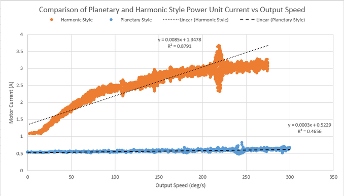
A few things to note in the graph above: First, the startup current is significantly higher in the harmonic drive version. The slope of the line is also significantly steeper in the harmonic style actuator. These are both because the harmonic drive that the actuator uses is a very high friction system. The motor must overcome both the static and kinetic friction in the harmonic drive to turn the output arm. This shows the main benefit of the planetary system. There is a smaller startup torque which barely increases over the operating speed range. This allows for a more efficient use of the battery power. The motor controller in use in the exoskeleton is rated for 5A continuous. The unloaded harmonic drive version used over half of that continuous current to simply move the actuator, severely limiting the potential power output of the system.
The other test that was performed on the actuator was a measurement of the output torque of the actuator versus input current to the motor. This was done by applying the current in the same fashion as the first test and monitor the output torque using an external load cell. The current was stepped at 1A increments and the torque measured and plotted below.
The other test that was performed on the actuator was a measurement of the output torque of the actuator versus input current to the motor. This was done by applying the current in the same fashion as the first test and monitor the output torque using an external load cell. The current was stepped at 1A increments and the torque measured and plotted below.
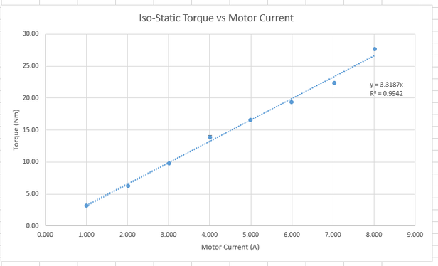
The slope of the line corresponds to the torque vs current relationship of the overall actuator. This was compared to the theoretical relationship derived using the Kt value of the motor and the gear ratio of the transmission. This relationship between the theoretical and actual values is the overall efficiency of the actuator. The efficiency experimentally calculated was found to match the theoretical efficiency value of 95%.
This result is vital for the future of planetary style transmissions in powered orthotic applications. The benefits of high efficiency and ease of back-drive-ability more than compensate for the slight reduction in output precision due to backlash and time invested into designing a custom system such as this one. Although I have finished this project, its impacts will live on in the lab that I worked in and hopefully influence the future course of powered exoskeletons.
This result is vital for the future of planetary style transmissions in powered orthotic applications. The benefits of high efficiency and ease of back-drive-ability more than compensate for the slight reduction in output precision due to backlash and time invested into designing a custom system such as this one. Although I have finished this project, its impacts will live on in the lab that I worked in and hopefully influence the future course of powered exoskeletons.
 RSS Feed
