After a brief hiatus from combat robot activity for academic reasons, I wanted to get back to what this blog was originally about, combat robotics. This post will not only be a combat robot related post, but it will also serve as a record of my typical design process. This post to showcases the entire design process from concept to competition. So buckle in, this is going to be a long post (or skip to the end if you just want to see the completed project.
I've wanted to make a spring powered flipper robot ever since I have been involved in combat robotics. I have always been fascinated with the obscure and different ideas in combat robots that could still be competitive. Spring powered flippers have always been in that niche for me. But the few people that have tried to make spring powered flippers have always been at best mildly successful. I'm making this post to show how much design work, iterations, and refinements go into something like this. And that's not to brag, but rather show that it takes a lot of work, but in the end it's worth it to make something cool.
I began my research years ago on youtube, looking for previous ideas to build my robot off of. I found the following two videos on youtube that later lead to this Ask Aaron post.
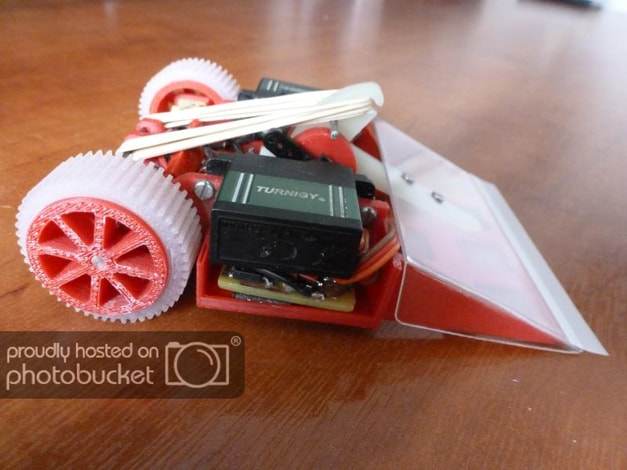
Both videos were very early concepts of a design like this, not finished projects. And both were just old enough to already be antiquated in the fast paced, ever evolving tech world of combat robotics. I loved the second video I found, It seemed perfect. It was an antweight robot that had a spring flipper. It was exactly what I wanted and it seemed to be powerful, although an unfinished iteration. Using the help from Mark on the previously linked Ask Aaron post I was off. I began drawing and making designs using my rudimentary Solidworks skills at the time and tried to make something that would work.
The design started with scouring through McMaster Carr to find an appropriate spring. It's been so long since I made this model I couldn't tell you what part it was. But I knew it had to have a couple pounds of force at full extension in order to have a good flip. This was because there was such a short distance over which the flipper could impart energy to the other robot in order to flip it. The problem with this is that looking at the equations on the Ask Aaron post I knew whatever motor setup I chose to spin the central cam to actuate the flipper arm would need to provide some serious torque. Using the second video I linked as a baseline, I decided to go with a continuous rotation servo motor with an additional set of gearing to provide enough torque to properly spin the cam that actuated the flipper arm. The problem with this setup is that it was extremely heavy. With 2 large steel springs, a big servo, and some gearing, there was just not enough weight to effectively build a robot around the setup in order to actually fit within the 1lb weight limit.
Because I could never get the robot under weight, the idea was filed away along with the many other failed ideas I had in the depths of my hard drive, to possibly be resurrected one day. Since then I had built another antweight, Hercules, and built many different versions of the robot, filling my desire for a lifting antweight robot. But the design always ended up leaving a little to be desired, as it won most of its fights by out-driving its opponents or surviving the multiple attacks. It is an interesting bot, but I knew I could build something bettern and more exciting.
Again through internet research I came across Dale's Homemade robots and his robot Dead Air. This page is a great read for anyone interested one building a spring flipper of any level. Dale does some amazing things in his robots, including some pretty intense machining as well as building his own custom control boards for his robots. This page was incredible and inspired me to return to my dreams of building a spring powered flipper.
Again through internet research I came across Dale's Homemade robots and his robot Dead Air. This page is a great read for anyone interested one building a spring flipper of any level. Dale does some amazing things in his robots, including some pretty intense machining as well as building his own custom control boards for his robots. This page was incredible and inspired me to return to my dreams of building a spring powered flipper.
I knew this was going to be a challenge. Dale in all his wisdom had struggled to meet weight for his spring powered flipper. I knew I would have to find some alternative solution that would help me to decrease my weight overall without the use of custom electronic boards that can monitor the current consumption of the motor to find the spot to hold the arm before firing. This did give me the idea to use a system to monitor the output though. In my original design, I had used a continuous rotation servo to turn the cam, completely defeating the point of using a servo. If I could find a way to monitor the cam angle, I could do the firing with the flip of a switch. I went down a long rabbit hole of searching through encoders and microcontrollers that would accomplish this continuous rotational feedback. But in the end, I decided the solution would be too fragile, too bulky, or above my knowledge at that point in the design process. Looking back now I could definitely accomplish this, and this likely would have been the route I chose had I not come up with an alternative solution.
I came across another legend in creative combat robot designs, Peter Waller. He had designed a UK ant (150g) flipper using rubberbands as the power source. However, the use of rubber bands was not what interested me about this design. The flipper worked through a very interesting mechanism that only had the servos turn 90deg at most. This process is detailed in another Ask Aaron post here. This setup separated the loading and firing operations into two different motions from the same servo. I loved this idea, but I would have to figure out a way to scale it up into a 1lb class as rubber bands and 3D printed trigger mechanisms likely wouldn't work at that scale.
Initial Flipper Design
Because this design centered around the flipper mechanism, I knew I would have to design that piece first and design the rest of the robot around it. The design I had in my head was sort of a combination of all of the previous ideas I had seen to build the best possible flipper mechanism. I had tried to design something around a snail cam, but in order to get the range of travel I would want, the mechanism would take up way too much of the overall weight of the robot as the size of the servo and overall mechanism increases with the range of travel of the flipper arm. Instead I wanted to use a single, non constant rotation servo to both cock and fire the flipper mechanism, similar to Pete's design. I also loved the use of a leaf spring as a source of potential energy in Dale's design. Many of the early designs I created used a coil spring similar to the original Janna video I found. Many of the springs that would provide the proper level of energy for a flipper over the small travel of the mechanism would be very heavy as they needed to be very stiff. A leaf spring could provide the same energy storage in a much more compact and light-weight package. Finally, I liked the form factor of the original Janna robot I found that started this. I wanted to make a two wheeled wedge style robot with a central flipping mechanism in the middle that would have a servo on one side to actuate the mechanism. These three bots would lead my design path for this bot.
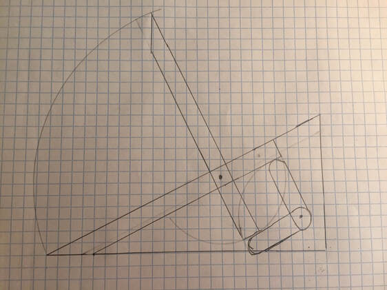
My go to first step in a design process is to draw things out on quartile paper. Especially for things on this scale it is really useful to draw things at a 1:1 scale to get a feel for how big the components will be in the end. My idea behind the flipper mechanism is that the flipper arm itself would pivot at around 2/3 of the length such that the distance traveled by the cocking mechanism would be roughly half of that of the tip of the arm itself. The servo would have an arm attached to it that would be centered when the flipper is in the cocked position. This would allow for using a self centering channel on my receiver to activate it. When the servo arm moves backwards the cocked flipper arm is released and the flipper fires. When the servo arm moves forward, it pushes the flipper arm out of the way to be able to move to the underside of the arm. A rubber band would pull the flipper arm back down so the flipper arm would snap over the servo arm once the servo arm gets low enough. As the servo arm returns to the neutral position, it catches the back end of the flipper arm to cock it back into place. You can see a drawing of the mechanism idea below.
My go to first step in a design process is to draw things out on quartile paper. Especially for things on this scale it is really useful to draw things at a 1:1 scale to get a feel for how big the components will be in the end. My idea behind the flipper mechanism is that the flipper arm itself would pivot at around 2/3 of the length such that the distance traveled by the cocking mechanism would be roughly half of that of the tip of the arm itself. The servo would have an arm attached to it that would be centered when the flipper is in the cocked position. This would allow for using a self centering channel on my receiver to activate it. When the servo arm moves backwards the cocked flipper arm is released and the flipper fires. When the servo arm moves forward, it pushes the flipper arm out of the way to be able to move to the underside of the arm. A rubber band would pull the flipper arm back down so the flipper arm would snap over the servo arm once the servo arm gets low enough. As the servo arm returns to the neutral position, it catches the back end of the flipper arm to cock it back into place. You can see a drawing of the mechanism idea below.
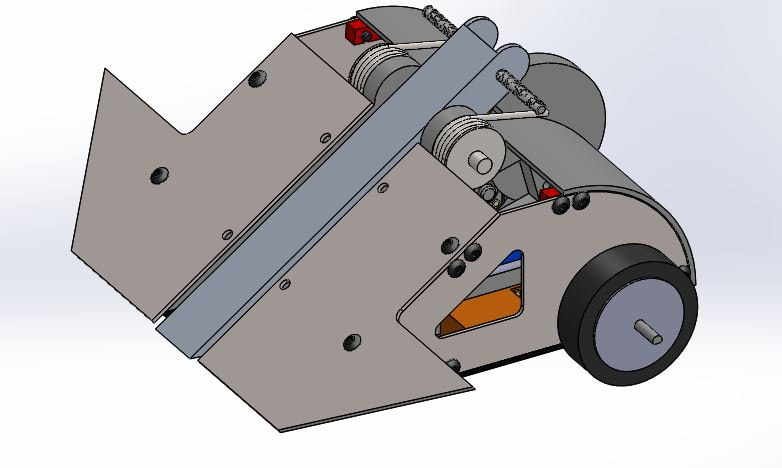
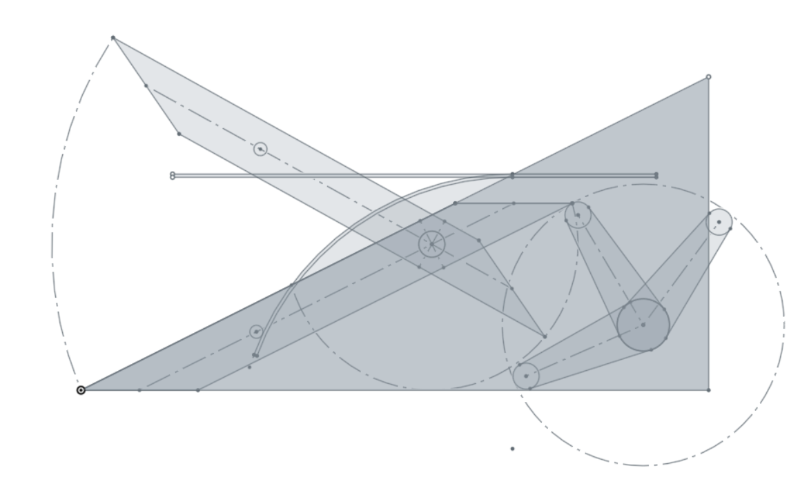
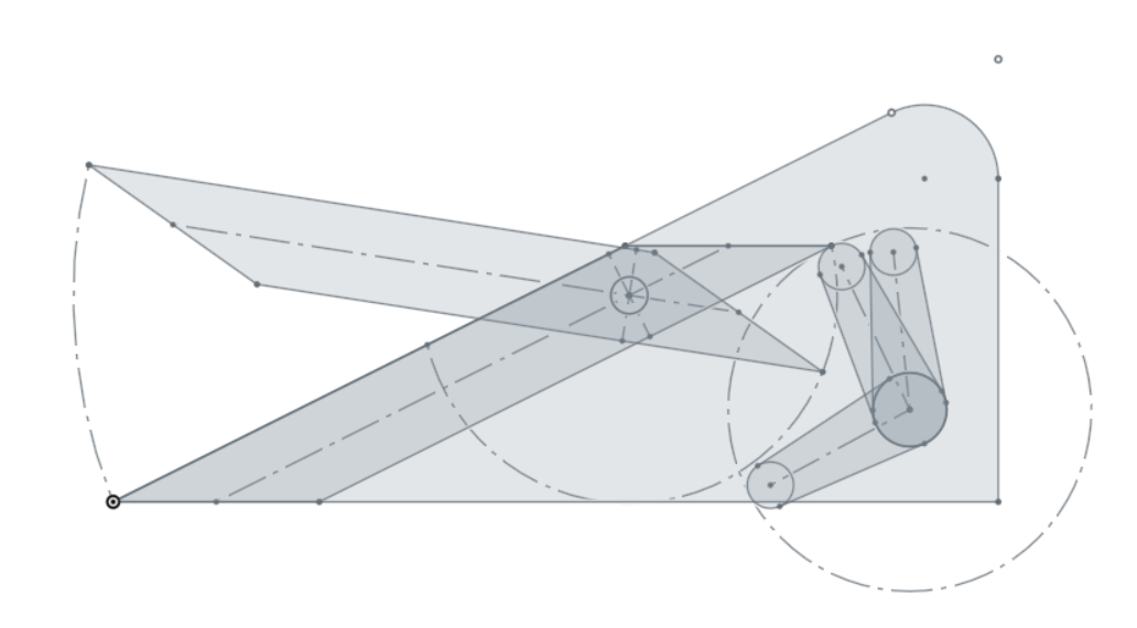
From here I went on to make a CAD version of the sketch to be able to lock down the actual dimensions and verify the interactions between the moving parts. You can see the initial sketch below:
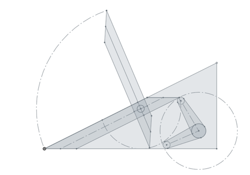
Here you can get a better idea of how the two arms interact. The large triangle is a rough depiction of the body. There are two sketches of each arm: the flipper arm in the cocked and fired position and the servo arm in the cocked and completely forward position. You can see from the arcs drawn in that there should be enough clearance for the flipper arm to pass back over the servo arm so that the servo arm can catch and reset the flipper arm to the down position.
It was at this time I realized that the positioning of the pivot for the flipper arm was almost exactly where I would want to put the drive motors for this robot. In order to fit the servo in place I planned on using a set of spur gears to transfer power from the servo to the trigger arm. I had considered this is some of the earlier designs as well in order to increase the output torque of the servo to actuate the original snail cam. I knew that Servo City sold servo gears, so that part was solved. The issue was the range of motion of the servo. By increasing the output torque of the servo, I would also limit the range of motion of the servo proportionally.
To specify the servo and the gears I needed, I first had to decide on how much flipper power I wanted. This is a little tricky to directly figure out given the geometry, but I can do a couple of simplifications and over spec the servo from these to be sure that it has the required torque. First I needed to decide on a spring to determine the force required to bend the spring. Going off of Dale's robot, his leaf spring flipper had around 70 oz-in of torque when fully bent. This seemed to work pretty well so I figured I would design around this number and make later adjustments if necessary.
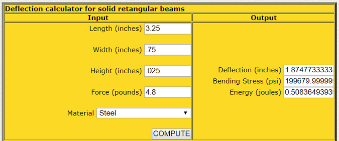
In order to design the spring for this specific application I used a combination of statics of a cantilever beam deflection and comparing it to the maximum bending stress to the yield stress of the spring steel. The same thing can be accomplished using Dale's online calculators of beam deflection and flipper power. This gave me a starting point of a leaf spring with the following dimensions:
From here I could figure out the power needed from the servo to actuate the flipper. Using the balance of torques around the main flipper arm pivot and the length of trigger arm I found the required torque of the servo to be around 96 oz-in of torque. This is a very conservative estimate using the maximum spring force and the full length of the moment arms. This is likely higher than the actual torque required for the trigger actuation, but is a good starting point to use. Using the HS225-MG servo as a baseline, the same servo I use in Hercules, I began to calculate the gear ratio I needed. The servo's stall torque at 6V is 66.6 oz-in. This means I would need a gear ratio of at least 1.44:1. Looking at the servo city gears I chose a 32T spur and 20T servo gear to create a 1.6:1 ratio for an output torque of 106.6 oz-in on the trigger arm. This servo has an out of the box max travel of 191 deg which, when put through the gear ratio, is reduced to 119 deg. This means a travel of only 59 deg per side which is less than the 83 deg required for the actuator to work. So I would have to find another servo.
Looking on Servo City I found the HS-7245MH Servo which is a digital programmable servo. This servo has a max input voltage of 7.4V meaning I could run it directly off of a 2S LiPo battery. It has a significantly higher stall torque of 88.9 oz-in meaning the gear ratio can be reduced to at least 1.08. I switched to a 24T spur and 20T servo gear for a ratio of 1.2:1. This servo only has a 180 deg range meaning without modification the servo would have a 150 deg travel which is only 75 deg each side. This is still too small for flipper to actuate correctly. The difference with this servo is that it is programmable. one of the features that can be programmed is the neutral point of the travel of the servo. This means that I could make one side of the travel of the servo higher than the other side. I could split is so the trigger would travel more than the required 83 deg in one direction and still have enough travel on the other side of the neutral point to be able to fire the flipper. The drawings of the servo with gears and the trigger arm travel are pictured below:
Looking on Servo City I found the HS-7245MH Servo which is a digital programmable servo. This servo has a max input voltage of 7.4V meaning I could run it directly off of a 2S LiPo battery. It has a significantly higher stall torque of 88.9 oz-in meaning the gear ratio can be reduced to at least 1.08. I switched to a 24T spur and 20T servo gear for a ratio of 1.2:1. This servo only has a 180 deg range meaning without modification the servo would have a 150 deg travel which is only 75 deg each side. This is still too small for flipper to actuate correctly. The difference with this servo is that it is programmable. one of the features that can be programmed is the neutral point of the travel of the servo. This means that I could make one side of the travel of the servo higher than the other side. I could split is so the trigger would travel more than the required 83 deg in one direction and still have enough travel on the other side of the neutral point to be able to fire the flipper. The drawings of the servo with gears and the trigger arm travel are pictured below:
 |  |
Component Selection
With the flipper geometry sorted out, the next step in my typical design process is component selection. Generally, since I have competed in this weight class before, I roughly know what components I want to use. My typical strategy is just go with what I know works and import the models into CAD and design around that. If the weight is too big, start doing weight reduction until everything works. While this is a valid strategy that has lead me to design a lot of successful bots in the past, this project was going to be a little more challenging. I knew from my past versions I was going to have issues meeting the 1lb weight requirement. To help try to prevent this eventuality I decided to be a little more meticulous in my design process than usual and have a spreadsheet that would help aid me in the weight calculations and component selections.
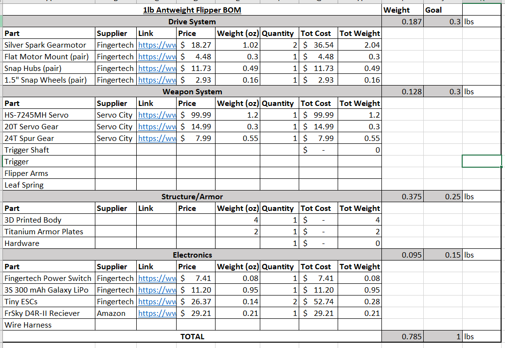
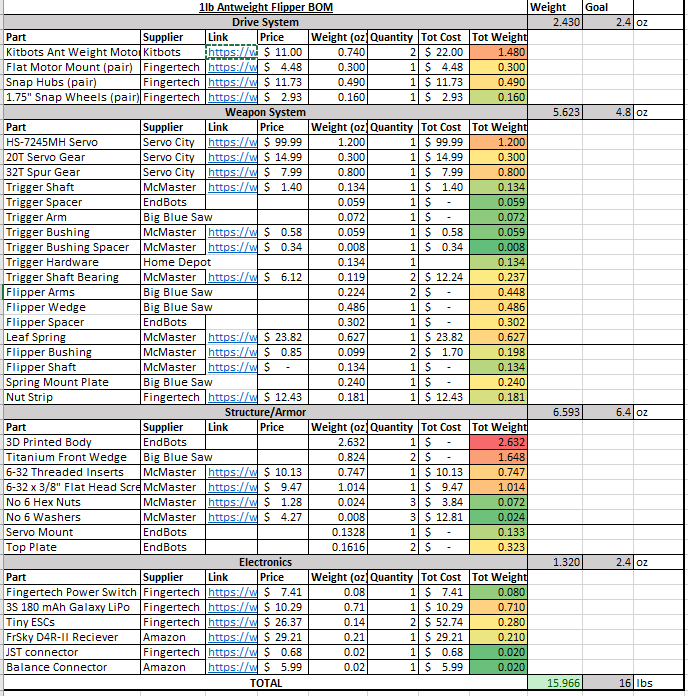
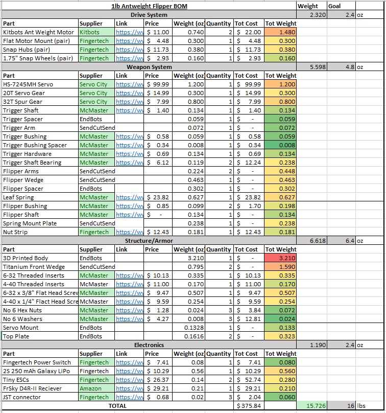
This picture represents an early version of the full BOM for the robot. I have seperated up the components based on their sub system. I have included the Riobotz combat robot tutorial recommended weight distributions for a balanced robot. My designs tend to be a little more durable than most so I tend to put more weight in the armor and structure than in the other subsystems. I imported a general set of components that I have used before (basically exactly what is in Hercules). I also added the selected servo and some initial guesses as to how much some of the other components will weigh. Overall, I was very happy with where this sat. As the design progresses, I planned update this spreadsheet with weights and prices to create a comprehensive BOM. But for now I was happy enough to continue on.
I used a lot of tested components in this design. I know they will work well together out of experience. The problem is that me just showing you readers this doesn't necessarily help to design your own robot. I have already broken down how I selected the weapon components. But I wanted to quickly go over how I would select the drive system and battery.
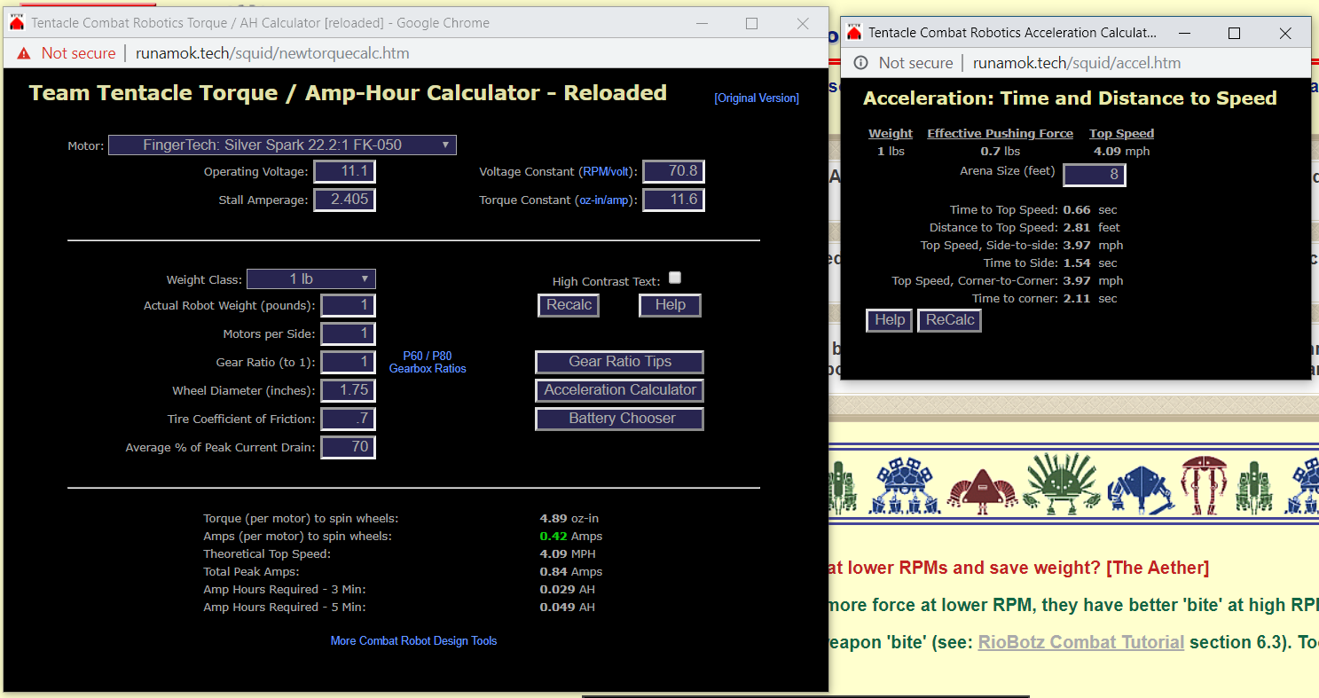
In general, this weight class is pretty limited on reliable drive motors. In my experience I have found the Fingertech silver sparks to be the most durable and versatile option for the price. There are other options that are tougher such as maxon motors, or cheaper options that can be found on eBay or other online retailers. But I found these motors to be very solid with decent performance for their size, weight, and cost. That being said, these motors are available in a wide range of gear ratios. You need to find the right combination of motor, gearbox, wheel size, and battery voltage to provide you with the right speed and pushing power. This can be a tough task. You need to take into account a lot of variables including operating voltage, motor constants, wheel diameter, stall current etc. There is a lot of math that goes into the selection of these motors. Fortunately for combat roboticists, Ask Aaron has developed a tool that helps to do all of this for you and actually provided some of the equations behind the tool if you click the "Gear Ratio Tips" button. This tool has a lot of the necessary values that are required to do these drivetrain calculations built in. It gives the user the key outputs based on the set up of your system to allow you to fine tune the speed of your robot and ensure the motors are running under stall. It also provides an estimate of how much current consumption these motors will use during a fight, however I have found this to be a very conservative estimate and generally at least double it when calculating battery capacity. Finally, there is an acceleration calculator that uses simple physics to tell you how quickly you will reach top speed and how fast you will cross the arena. I generally shoot for around two seconds. Below is the output of these tools for my selected setup:
I used a lot of tested components in this design. I know they will work well together out of experience. The problem is that me just showing you readers this doesn't necessarily help to design your own robot. I have already broken down how I selected the weapon components. But I wanted to quickly go over how I would select the drive system and battery.
In general, this weight class is pretty limited on reliable drive motors. In my experience I have found the Fingertech silver sparks to be the most durable and versatile option for the price. There are other options that are tougher such as maxon motors, or cheaper options that can be found on eBay or other online retailers. But I found these motors to be very solid with decent performance for their size, weight, and cost. That being said, these motors are available in a wide range of gear ratios. You need to find the right combination of motor, gearbox, wheel size, and battery voltage to provide you with the right speed and pushing power. This can be a tough task. You need to take into account a lot of variables including operating voltage, motor constants, wheel diameter, stall current etc. There is a lot of math that goes into the selection of these motors. Fortunately for combat roboticists, Ask Aaron has developed a tool that helps to do all of this for you and actually provided some of the equations behind the tool if you click the "Gear Ratio Tips" button. This tool has a lot of the necessary values that are required to do these drivetrain calculations built in. It gives the user the key outputs based on the set up of your system to allow you to fine tune the speed of your robot and ensure the motors are running under stall. It also provides an estimate of how much current consumption these motors will use during a fight, however I have found this to be a very conservative estimate and generally at least double it when calculating battery capacity. Finally, there is an acceleration calculator that uses simple physics to tell you how quickly you will reach top speed and how fast you will cross the arena. I generally shoot for around two seconds. Below is the output of these tools for my selected setup:
Initial Layout
With all of the purchased components selected, it was time to start actual design process. Again, for this I generally start with a 1:1 sketch on graph paper of the layout of the robot as a whole. I knew the rough dimensions of the flipper module, so the design would have to be built around that. I knew the general layout and shape in my head, but I always try and draw it on paper first to get a general idea of how big things need to be. I started with a top view of the robot.
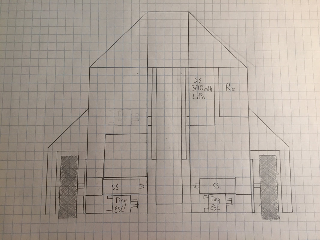
This view allows me to make sure all of the internal components have enough space to fit inside of the robot. You can see most of the components that I listed in the BOM in this view. There seems to be plenty of space given how long the flipper unit is. The overall dimensions of this layout from this drawing are 7" x 6", which a little big for this weight class, but not too much bigger than my other antweight. I will just have to be careful to not make it too big for weight and durability purposes.
Obviously this layout and dimensions aren't final, but help to provide me a good starting point. For example The flipper unit will likely be a little wider than it is here to give a little more clearance for the arm side to side. I will also likely move as many of the internal components towards the back as possible to help with weight distribution. This will also allow me to route the wires between the two sides easier as there is a gap between the servo and the flipper arm where I could make a wire channel.
Just a few design features to note on this. For the drivetrain, the wheels stick out the back side of the robot to allow the robot to drive when on it rear to hopefully help self righting. I had also planned to print a few removable wheel guards to help protect the wheels and allow me to reconfigure the armor to help fit the opponent. There are some nasty horizontal spinners in this weight class that I will have to be prepared for. Another design consideration to help protect from spinners is the front wedge. I plan to have a set of sloped titanium plates in the front to help deflect hits from spinners. The plan right now is to have them angled both towards the front and the sides to act as a wedge and deflect hits from other robots. This might change in the future if I have more weight to put into the wedge to help better protect the rest of the body.
CAD Design
With the basic size and shape locked in, I began to create a 3D CAD model of the robot. This process had many different design challenges that I will detail in this section of the post. The 3D printed frame of the robot was going to be rather complex in order to take advantage of the 3D printing process as much as possible. I started with a general layout from the initial hand sketches. I then began adding internal components starting with the drive components. When all of the internal components were modeled and fit into the body of the robot I could begin designing the rest of the manufactured components of this design. The wedges, top plates, and motor mounts are all attached to the frame using heat set inset inserts for thermoplastics. All of the metal components were initially designed to be 2mm titanium to save on manufacturing costs. This was later changed for weight savings. The next major design step was to model and verify the custom leaf spring. This meant redoing all of the calculations several times to optimize the setup. Finally, the fasteners were all added and the BOM updated. Several design changes were made to make weight as can be seen in the album below:
Body Design
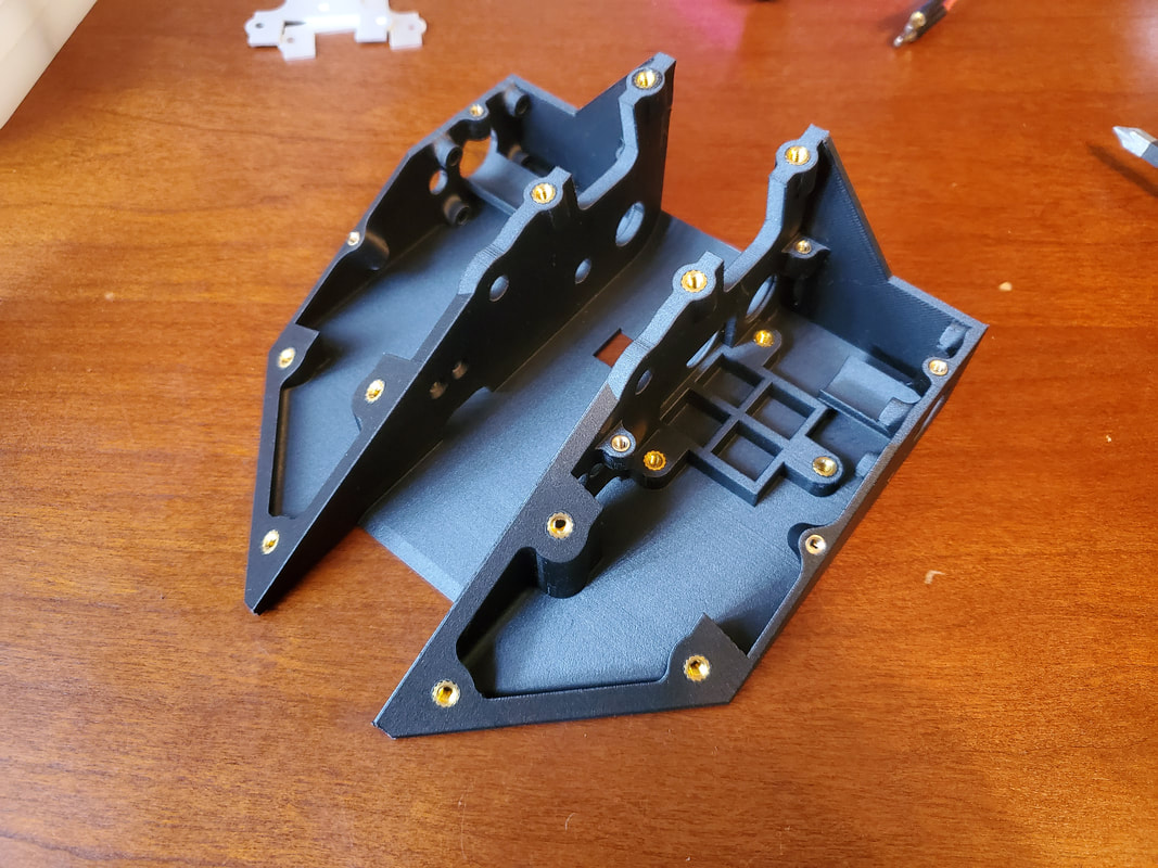
The main frame piece of the robot is designed to be a single piece printed from reinforced nylon. Because nylon doesn't hold threads well, all of the places where components are bolted to the frame are designed in a way to have heat-set threaded inserts. There are around 30 inserts in total as there are a lot of screws holding everything together. The outer walls of the body are .1" thick and the central walls where the flipper mechanism is are 3/16" thick. The threaded inserts need .310" of material to be fully inserted. In order to save weight, most of the threaded insert locations are simply circular extrusions to provide enough material to properly hold the inserts.
The weapon servo and drive motors each have their own specific mounting points in the body. The servo has a platform that it sits on to space it properly relative to the rest of the flipper components. A custom 3D printed harness holds the servo in place. The drive motors are face mounted using the fingertech mounting plates. In order to support the back end of the motors, each motor has its own platform to sit on. The idea is to ziptie the drive motors to these platforms as a form of shock mounting in as small and light weight of a design as possible.
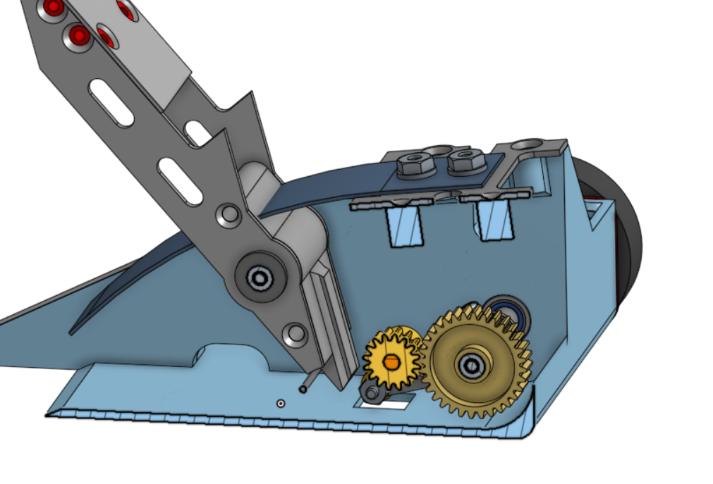
Flipper Design
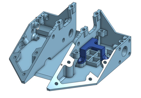
The flipper has always been the biggest design challenge of the build. I did a lot of initial calculations to ensure that the final design would require as little tweaking as possible to fully integrate the flipper into the final design. Looking at the cross section above you can see that the overall design is relatively the same, with a few key changes. First, the servo gear was moved up off the base. This was done to ensure the gear had clearance from the base plate as well as re-position the servo relative to the other internal components. One of the major changes to the overall layout is that the spring base is angled slightly. This was done to optimize the spring geometry in order to keep the maximum stress during bending under the yield stress of the material. This required the calculations for the spring deflection, flipping, and servo power to be re-done and verified again.
The flipper has always been the biggest design challenge of the build. I did a lot of initial calculations to ensure that the final design would require as little tweaking as possible to fully integrate the flipper into the final design. Looking at the cross section above you can see that the overall design is relatively the same, with a few key changes. First, the servo gear was moved up off the base. This was done to ensure the gear had clearance from the base plate as well as re-position the servo relative to the other internal components. One of the major changes to the overall layout is that the spring base is angled slightly. This was done to optimize the spring geometry in order to keep the maximum stress during bending under the yield stress of the material. This required the calculations for the spring deflection, flipping, and servo power to be re-done and verified again.
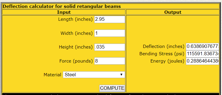 |  |
I struggled with this part as there is little readily available data on the actual yield stress of hardened spring steel as it varied greatly depending on heat treatment. The spring values shown above are again based on the values that Dale used as those provided a good flip without bending the leaf spring. I found the bending stress of his setup to be 120 ksi so I set that as my bending limit. Ideally the spring would provide a high force over a high range of motion to provide the best flip. The issue is the greater the spring force, the greater the bending stress. In order to compensate and lower the bending stress, the deflection has to be lowered. This optimization problem results in the ideal leaf spring being a long, wide plate in bending. This would be very heavy though. I ended up with the above geometry to meet the specifications of Dale's flipper as a starting point that could be adjusted in later versions.
To verify that the same servo can still be used, the same analysis had to be done with the final setup. Using the same basic calculations as before: the spring force is 8 lbf at the flipper; the force on the other end of the flipper arms would be around 10.5 lbf; the trigger arm is 1.25" long meaning the torque required on the trigger arm is 13.1 in-lb (210 oz-in); with a 1.33 gear reduction that would mean the servo would have to produce 157 oz-in of torque. This is significantly higher than the 89 oz-in stall torque of the servo. However, this is an overestimate of the required torque as it assumes the maximum force perpendicular to the moment arm of the trigger. The trigger is designed in a way that there is no torque on the arm to maintain the loaded position when the spring force is at its highest. A more careful analysis of the forces involved would give an accurate representation of the maximum torque required to load the flipper.
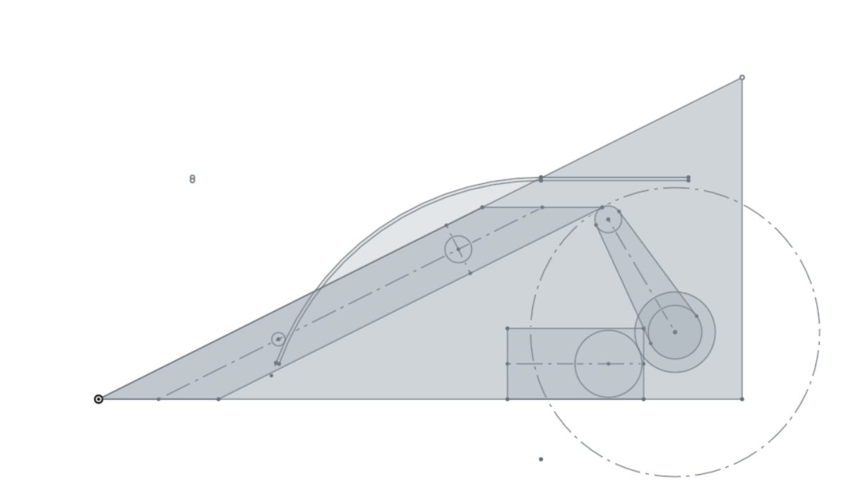
The first step I had to take was to update the initial flipper sketch. This would allow me to more easily see the interactions between the parts all at once. I assumed based off of the fact that the initial theoretical calculations showed a big difference between the servo torque and the torque required, I'd likely want to increase the gear ratio. With the rest of the components set I knew I'd have space to make the servo gear smaller, which also had the added benefit of decreasing the weight overall. Switching to a 20T servo gear and a 32T spur gear created a 1.6:1 reduction. Using the final flipper sketch below, I verified that with the increased reduction, the servo would still have enough travel.
To verify that the same servo can still be used, the same analysis had to be done with the final setup. Using the same basic calculations as before: the spring force is 8 lbf at the flipper; the force on the other end of the flipper arms would be around 10.5 lbf; the trigger arm is 1.25" long meaning the torque required on the trigger arm is 13.1 in-lb (210 oz-in); with a 1.33 gear reduction that would mean the servo would have to produce 157 oz-in of torque. This is significantly higher than the 89 oz-in stall torque of the servo. However, this is an overestimate of the required torque as it assumes the maximum force perpendicular to the moment arm of the trigger. The trigger is designed in a way that there is no torque on the arm to maintain the loaded position when the spring force is at its highest. A more careful analysis of the forces involved would give an accurate representation of the maximum torque required to load the flipper.
The first step I had to take was to update the initial flipper sketch. This would allow me to more easily see the interactions between the parts all at once. I assumed based off of the fact that the initial theoretical calculations showed a big difference between the servo torque and the torque required, I'd likely want to increase the gear ratio. With the rest of the components set I knew I'd have space to make the servo gear smaller, which also had the added benefit of decreasing the weight overall. Switching to a 20T servo gear and a 32T spur gear created a 1.6:1 reduction. Using the final flipper sketch below, I verified that with the increased reduction, the servo would still have enough travel.
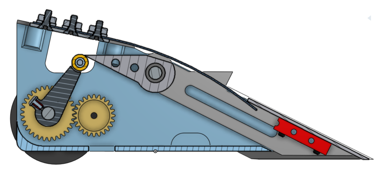
As you can see, the trigger has clearance on both the firing and reset sides even with the higher gear reduction. With the geometry settled it was time for the more challenging task of dynamic analysis. I debated how much of this to include on this post as it is a blog and most people don't come here to look at algebraic equations. I have included a photo of my calculations as well as a screen shot of the excel spreadsheet and output graph below for reference purposes. I won't go into too much detail on the actual mathematics and physics, but it is there if you wish to look at it. I ended up including it on here to show first how difficult of a problem designing a spring flipper is, but more importantly to help anyone in the future who uses this as a guide to make their own flipper robot.
You can see from the graph above that the peak torque required of the trigger arm is around 127oz-in. With the 1.6:1 gear reduction, that would mean that the servo would require at least 79oz-in of torque to fully reload the mechanism. This is less than the stall torque of 89 oz-in of the servo selected, but very close to stall. This means the servo would likely struggle to quickly reload the mechanism ,especially with any frictional losses in the system. However, I was already starting to push the limit of what I could do geometrically to lower this torque while still operating within the usable output range of the servo. So i decided this was a good starting point, and that if the servo stalled out during testing, I could easily remedy this by trimming down the spring slightly to decrease the flipper force and thus the load on the trigger.
Weight Reduction
The final phase of the design process was weight reduction. As I mentioned earlier, this has always been a major struggle of this design. All of the previous versions of this design were significantly overweight. Finding the proper weight balance is difficult for flippers at any weight class because you have to store enough energy to launch your opponent without a spinning component. This doesn't leave a lot of weight for armor. Typically flippers have rather thin armor to make weight.
The initial BOM I did showed that I would likely have an easier time making weight with this design than designs of the past, however this was still a major task. I had used roughly the same internal components on Hercules which made weight just fine. The major difference is that this design has a lot more metal in it as parts of the from wedge and flipper arm. Having a large steel spring didn't help either.
One of the main questions that came up during this process was how to estimate the weight of the 3D printed body. Having the CAD model is helpful as I know the volume of the part, but when 3D printed, the part won't be solid. There are typically multiple wall layers printed around the perimeter and a set percentage of infill inside of that. In order to estimate this without actually printing the part, I created a formula to estimate 25% of the weight as solid to represent the walls of the print, and the remaining 75% based off of the infill percentage that could be adjusted to cut weight.
The initial design pictured below weighed in around 1.25 lbs with fasteners. I knew I would have to take some drastic measures to make weight, but it was definitely doable.
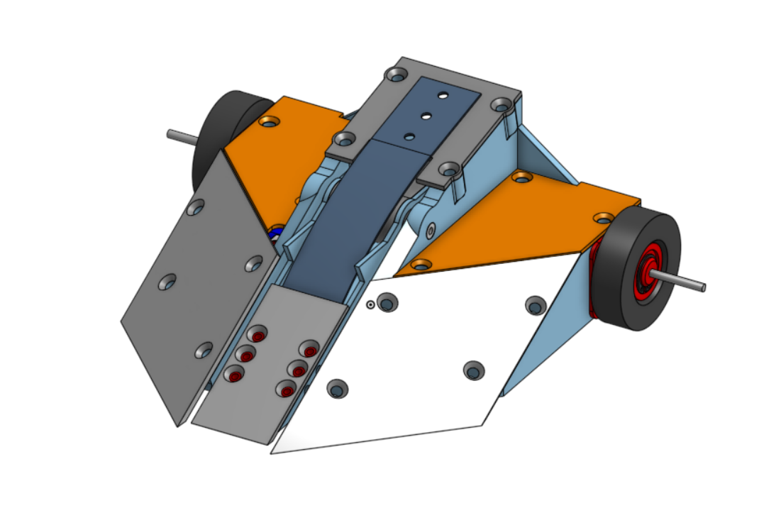
First, I cut the front wedges almost in half to take out a large amount of the titanium. I thinned out all of the titanium from 2mm to 1/16". I went through and thinned out a lot of the walls of the body to cut down on the weight. In addition I cut out a lot of the unnecessary material from under the wedges, motors, and servo. All of this was still not enough. I swapped the motors from silver sparks to Kitbots antweight motors that saved around a half an ounce total. I also swapped out the battery for a smaller capacity. I changed the material of the trigger and weapon shaft to aluminum as well. When the weight was close enough and a lot of the other weight reduction methods had been implemented, I started cutting down the percentage of infill on the body until the total weight was under 16oz. The final design and BOM with weights can be seen below.
Construction and Initial Testing
Because I spent so much time meticulously planning this build instead of rushing through it like I have for some of my other builds, the ordering of parts went relatively smoothly as I had an updated BOM. Because this was a 3D printed unibody design I wanted to start this build with a test print of the body and make sure that all of the electronics and other purchased parts mated properly to the body. Because this was mostly for the form of the bot and not for durability I got a body printed by 3DHubs out of PLA relatively cheaply.
The print came out great. Just like I drew it up in CAD. I'm always still impressed with how intricate 3D prints can be.
I started by heat setting the threaded inserts into the body to mount the motors with. This all fit fine so the next major step was the electronics.
Electronics
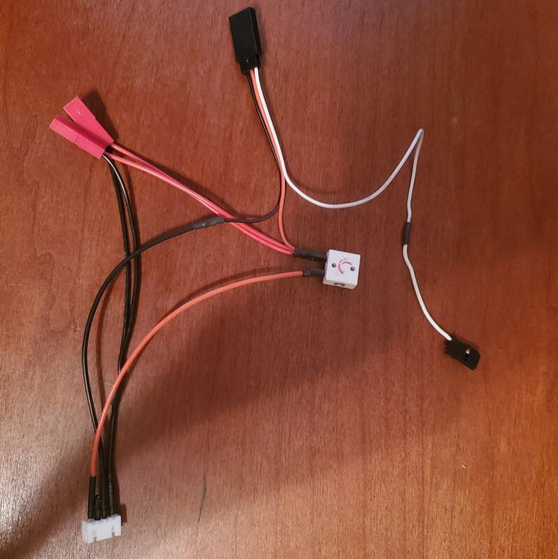
Because this robot was split into two electronics bays by the part in the middle where the flipper goes, I had planned on running wires between the two halved through a little cutout in the central walls. You can see the wires running across in the last image in the album above. Because of this, I ended up adding JST connectors to the power lines of the ESCs so that the wires running across wouldn't have to be soldered together inside of the bot, especially since this would be a 3D printed chasis. I learned that lesson from all of my electronics failures with Barrel Roll.
My original plan was to have the drive motors run on 3s LiPo and have the servo for the weapon motor run on 2s LiPo that I tapped from the balance plug of the battery. As a note, this is not recommended for the reason that this could potentially make the cells of the battery unbalanced from one another leading to decreased battery life or potential catastrophic battery failure. That being said, I knew the risks of the setup I was attempting to make and still planned on doing so because the servo has a relatively low current consumption in comparison to the drive motors, so the cells should not become too unbalanced. When I charge my batteries, especially the small ones, I balance charge them so that should fix the batteries between matches. If during testing they became so unbalanced that I was worried about them, I would resort to a backup plan of running the whole robot on 2s.
I started by heat setting the threaded inserts into the body to mount the motors with. This all fit fine so the next major step was the electronics.
Electronics
Because this robot was split into two electronics bays by the part in the middle where the flipper goes, I had planned on running wires between the two halved through a little cutout in the central walls. You can see the wires running across in the last image in the album above. Because of this, I ended up adding JST connectors to the power lines of the ESCs so that the wires running across wouldn't have to be soldered together inside of the bot, especially since this would be a 3D printed chasis. I learned that lesson from all of my electronics failures with Barrel Roll.
My original plan was to have the drive motors run on 3s LiPo and have the servo for the weapon motor run on 2s LiPo that I tapped from the balance plug of the battery. As a note, this is not recommended for the reason that this could potentially make the cells of the battery unbalanced from one another leading to decreased battery life or potential catastrophic battery failure. That being said, I knew the risks of the setup I was attempting to make and still planned on doing so because the servo has a relatively low current consumption in comparison to the drive motors, so the cells should not become too unbalanced. When I charge my batteries, especially the small ones, I balance charge them so that should fix the batteries between matches. If during testing they became so unbalanced that I was worried about them, I would resort to a backup plan of running the whole robot on 2s.
 | 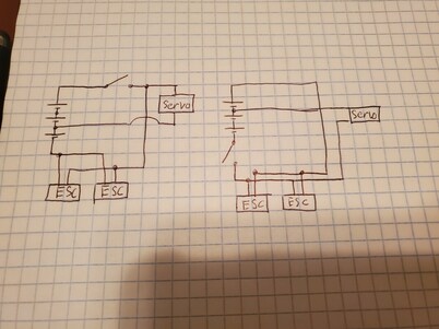 |
You can see above my planned electronics setup. I initially created a wiring harness like the diagram on the left, but this only worked on paper. The concept makes sense looking at the diagram, but when I went to plug everything in the drive ESCs were still receiving power even though the switch was off. I found out that by unplugging the servo, the ESCs lost power. This lead me to conclude the ESC was getting power through the servo. I assumed it was because I had wired the servo to the first two cells so the "ground" for the servo was not at the same voltage as the ground for the ESCs. I went ahead and remade the wiring harness to look like the diagram on the right to follow my hypothesis only to find the same issue was present. After asking some fellow builders and not getting any clear responses on how to solve this issue, I decided to try and add a diode to the servo's power line to prevent the power from running back through the servo to power the ESCs. This worked to keep the ESCs off when the the switch was open. But caused issues with the motors during my test driving. The motors would occasionally keep running after I had stopped moving the stick on the controller. This is not good for both safety reasons and the fact that this would make the bot significantly harder to control in battle.
At this point I had a couple of options to fix this issue. I could have added a second power switch to control the power to the servo to isolate the circuits and likely fix most of my issues. But because I was already so close on weight, I decided to go with my backup plan to run the entire system off of 2S LiPo. This would both fix my electrical issues and lose some weight from the robot. I would have a lower top speed but in drive testing this seemed to be just fine.
At this point I had a couple of options to fix this issue. I could have added a second power switch to control the power to the servo to isolate the circuits and likely fix most of my issues. But because I was already so close on weight, I decided to go with my backup plan to run the entire system off of 2S LiPo. This would both fix my electrical issues and lose some weight from the robot. I would have a lower top speed but in drive testing this seemed to be just fine.
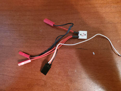
Above you can see the final power harness for the robot. The positive lead of the battery goes through the switch to power all of the components. You can see all of the connectors here that connect to the battery, ESCs, and servo from top to bottom. I put mating JST connectors on the ESC as mentioned before for easy disassembly. The signal lead of the servo was separated in order to go to the receiver along with the servo leads of the ESCs.
With everything wired I took a little drive test around my kitchen that seemed to go well
With everything wired I took a little drive test around my kitchen that seemed to go well
With the electronics sorted, I could move on to other things. During assembly I noticed a few minor things that needed to be added to the print to make assembly easier. I also realized how big 6-32 screws looked on this robot. I want to keep them for the front wedge as there are only 3 holding the whole thing on. But I planned to replace the screws for the motor mounts and top cover with 4-40s to save weight. With the updated BOM below it was time to order the metal parts and test fit those and begin the flipper testing.
Full Assembly
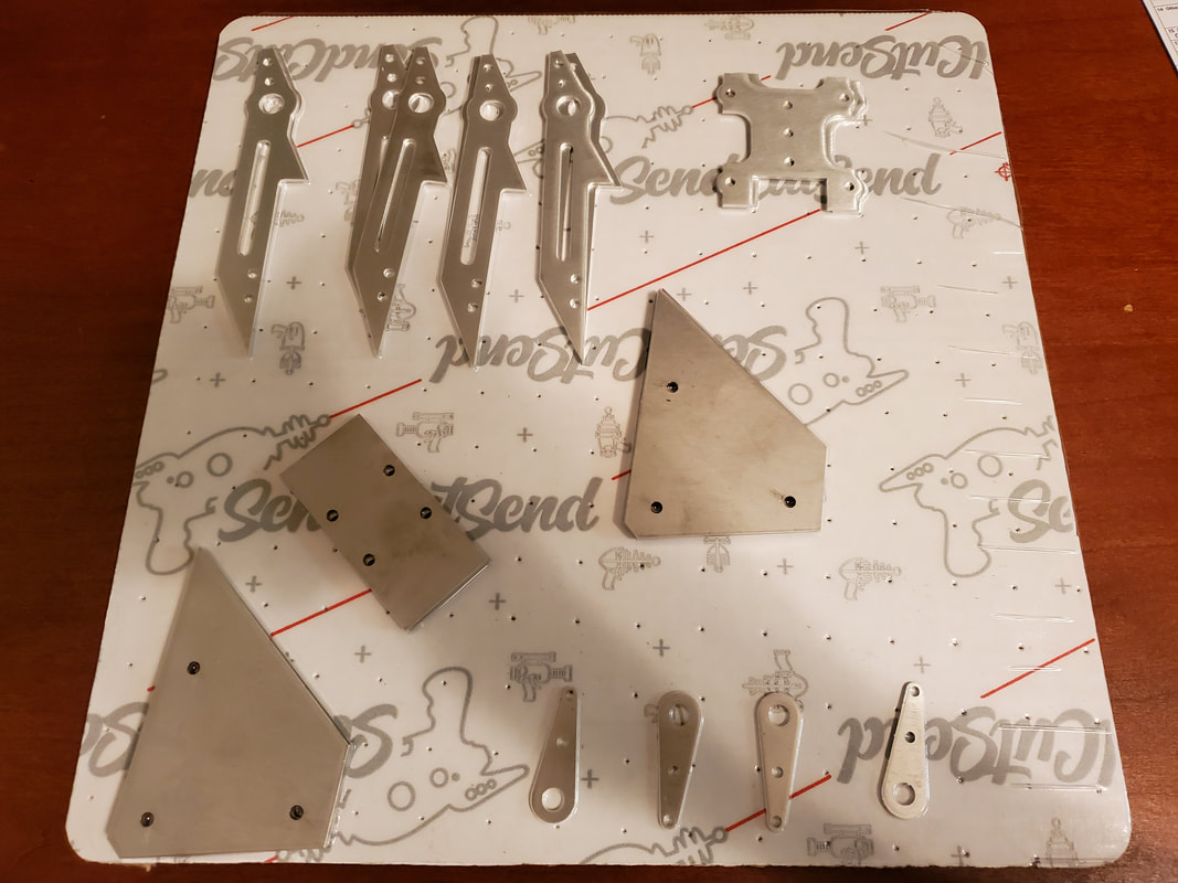
After doing the test fit of the electronics and doing the final revisions on the design, I ordered the manufactured parts. The main 3D printed parts came from 3D Hubs and the metal pieces came from Send Cut Send. Both excellent resources for quick manufactured parts. 3D hubs does a little bit of everything, but I use them for their 3D printing services, specifically their carbon fiber reinforced nylon for most of my 3D printing services. Send Cut Send does instant quoting of laser cut pieces with a wide variety of material options. Most of these pieces were aluminum or titanium, but I also got some new AR500 weapon discs for Butcher that I will update on later. I've included some pictures of the pieces that were made below:
 |  |
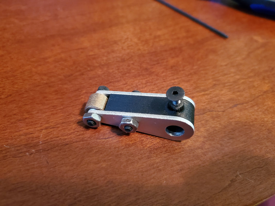
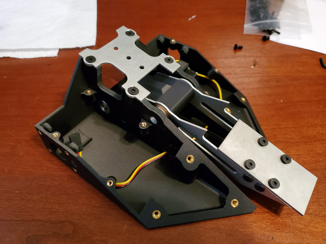
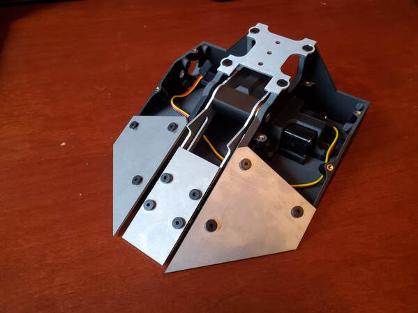
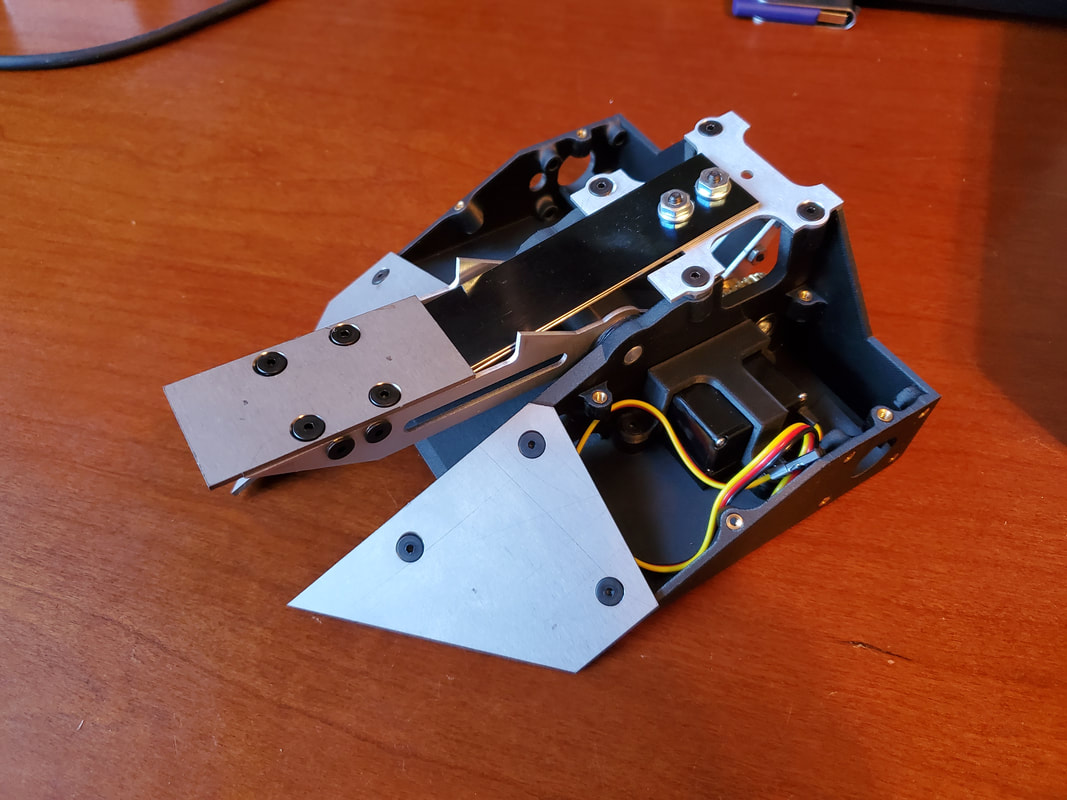
I started by making the sub-assemblies for the bot. I installed heat set inserts into the body and made sure the servo fit in its designed location. I assembled the flipper arm and the flipper trigger seen below:
 | 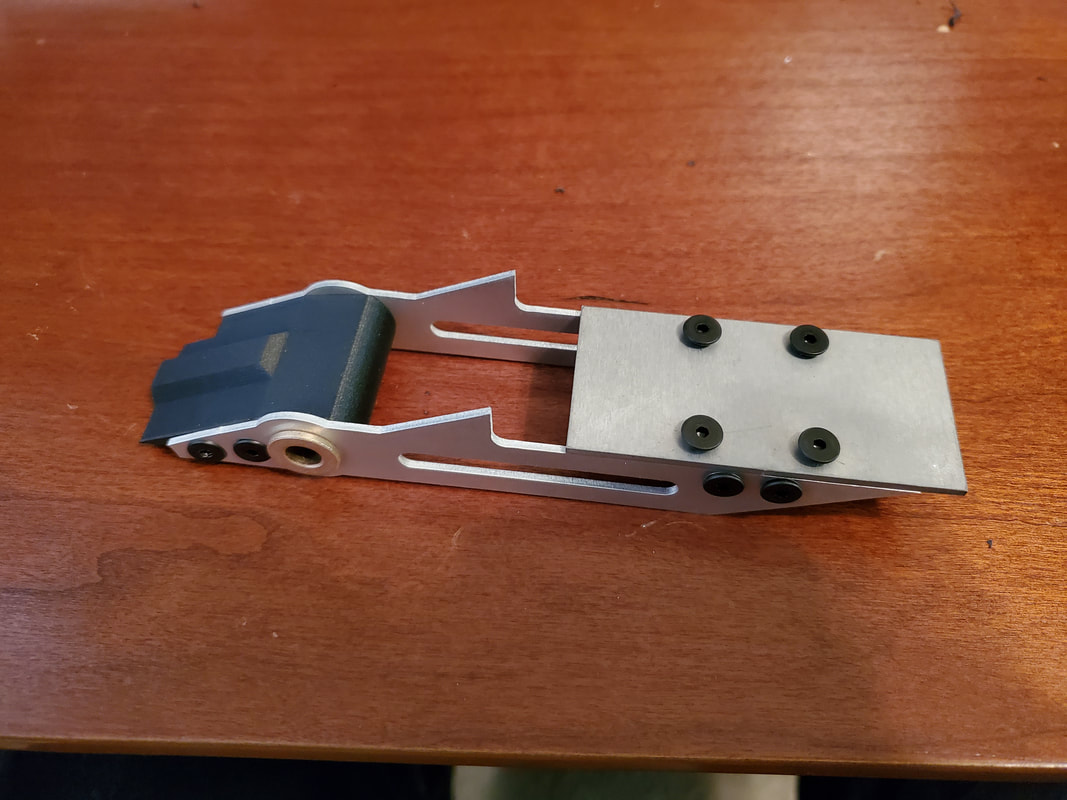 |
I found my first design oversight when I tried to assemble the flipper. I didn't leave enough clearance between the top of the flipper arm and the boss that holds the screws for the plate that holds the leaf spring. If the arm is not perfectly centered on the bot, the arm contacts these and is unable to lower completely. See below:
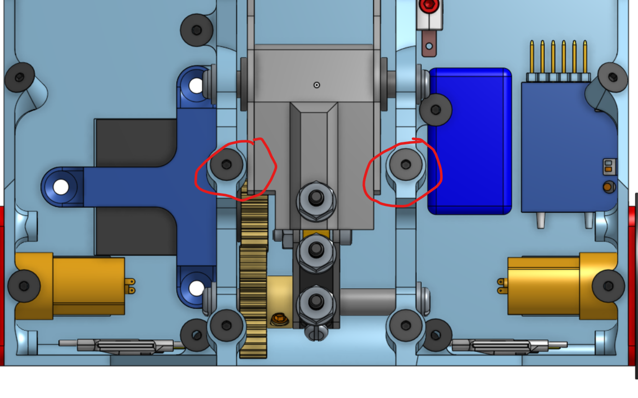 |  |
This is definitely something that needed to be addressed so this doesn't happen in combat. I planned to add some washers to the flipper shaft to minimize the possible horizontal movement of the arm along the shaft. But this still didn't leave enough spacing in my opinion. For testing purposes I trimmed the arms to add some extra clearance, but this would require a redesign to work properly.
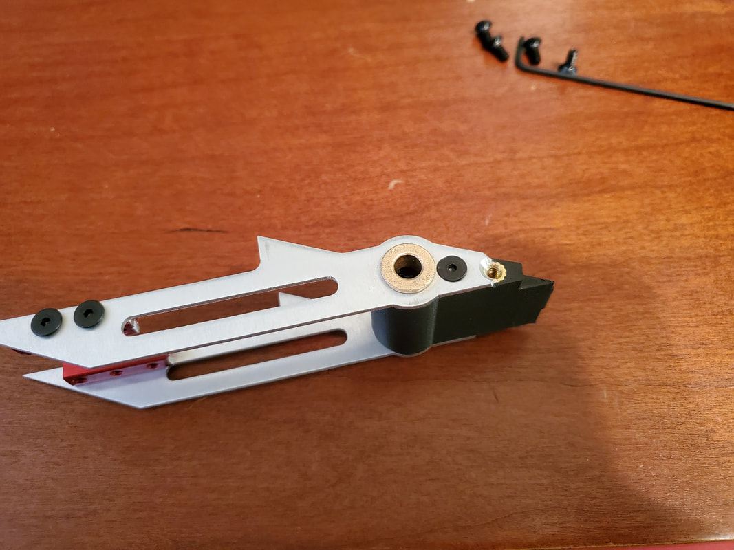
After cutting the tips off the arms (see below) and adding washers to the sides of the weapon arm shaft, the arm goes up and down much more smoothly. There's still not a lot of clearance there, but if there's enough force on the arm to bend the shorter end of the arm to the point where it would interfere, there's likely going to be clearance issues on the other end as well so I'm not too worried about it.
I made a couple of leaf springs for the flipper out of 1095 spring steel. This stuff is no joke to machine. I bought a real sheet metal hole punch to cut the holes for the screws which just barely does the job and sounds like a gunshot every time it punches a hole in the spring steel. I'll likely look into alternative ways to retain the spring in the future so this is easier to do. But for now, I only punched two holes in there to save some weight and make it easier to get hole alignment to the spring mount.
I made a couple of leaf springs for the flipper out of 1095 spring steel. This stuff is no joke to machine. I bought a real sheet metal hole punch to cut the holes for the screws which just barely does the job and sounds like a gunshot every time it punches a hole in the spring steel. I'll likely look into alternative ways to retain the spring in the future so this is easier to do. But for now, I only punched two holes in there to save some weight and make it easier to get hole alignment to the spring mount.
 |  |
With the springs cut I could do some testing with the flipper. I still don't have the proper end tapped shafts I need to properly retain the trigger system, and I had been having trouble programming my servo as intended, so the testing had to be done by hand. In the video below I'm wearing safety glasses and only putting my hands where I can't get my fingers pinched. This flipper mechanism isn't quite as dangerous as a spinner, but safety is still a concern.
I started my testing with just one leaf spring and it was rather lackluster. It somewhat flipped, but only barely better than a servo would. I did two things to help this: one I added another spring on top of the current one to increase the spring force. This definitely helped, not quite doubling the flip, but a definite improvement. I'm not sure if I'll have the weight for this on the final version, but I'm going to leave it for now. The second thing that I did was add spacers under the front of the spring mount to increase the relative angle between the base of the spring and the arm, increasing the deflection and the force at the bottom of the stroke. This helped pretty significantly, even with one spring. The initial math that I did says that this should plastically deform the spring so that they are bent downward, but there doesn't seem to be any deformation so I plan to keep this until the next version of the body where I can change the angle.
Here is a video of the flipper in action. As you can see, the arm doesn't go down all the way. I would have to either shim or reprint the central spacer to the flipper arm so that the interaction with the trigger fully lowers the arm in the loaded position. This would end up being a part of the flipper arm redesign.
After working my way through the servo programming software, I was able to do a proper test of the flipper mechanism. This is the servo programmer that I used to adjust the end points of my servo. It worked after I figured out the confusing GUI and very specific plug in process. This is an option, but if you're reading this and considering re-programming your servos, I would recommend looking for a better servo programmer if there is one out there.
The video of the test below shoes the mechanism working mostly as intended, but there were some issues. If you notice there is only one spring and no spacers on the spring mounting plate. This is because the servo was to weak to handle any more spring force and still operate as intended. This lead to a very lackluster "flip" that didn't do anything but lift the robot quickly, not flipping it over as intended. This isn't in the video, but trust me you didn't miss anything.
The video of the test below shoes the mechanism working mostly as intended, but there were some issues. If you notice there is only one spring and no spacers on the spring mounting plate. This is because the servo was to weak to handle any more spring force and still operate as intended. This lead to a very lackluster "flip" that didn't do anything but lift the robot quickly, not flipping it over as intended. This isn't in the video, but trust me you didn't miss anything.
After seeing this, I decided that I would have to go back and redesign the flipper mechanism to have enough power to flip something the way it was intended. This meant redesigning most of the robot. This wasn't really a concern though as the event that I was intending to attend with this bot was cancelled for COVID-19 so I have plenty of time to redesign and refine this bot so it worked for whatever event it eventually attends. Additionally there were a lot of small changes that I wanted to implement into the design that I found out in the construction of this version.
Drop Test 1.1
Since I've already run through the details of this design process earlier in this post, I'll run through it quickly here and highlight the major improvements that I plan to implement in the next version.
This starts with increasing the power of the flipper. From the video above you can see the geometry works really well. The only problem was that the arm didn't go quite low enough to clear the fixed wedge. This is a simple fix by shimming the flipper arm spacer a little when I reprint the center piece.
The main problem was the spring power. Doing the tests it seems like 2 springs provided a really good flip. So I used that as a baseline. Having 2 springs would be heavy, but I wanted to try and have that option If I could to maximize flipping power. I also noticed that the spring was no where near plastically deforming as my initial math would suggest. So I decided to increase the angle between the spring mount and the flipper arm when loaded. This would further increase the flipping power, potentially to the point where I could still get a really good flip with only 1 spring.
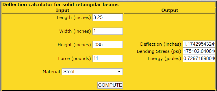

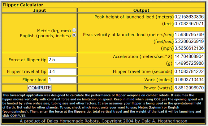
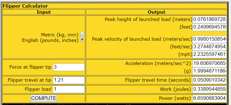
These two screen shots show the updated geometry outputs from the two calculators on Dale's website. By changing the angle, I could increase the deflection of the spring, and thus the force of the spring from 4.8 lbf last time to 11 lbf this time, over double the previous version. This meant that I could theoretically get 2x the flipping power with only one spring, or 4x power with two springs if I have the weight. The second photo shows the results of the new dual spring setup, showing the max flipper height would be around 1.5 feet in the air which is really impressive at this scale.
With this as the lofty goal I was trying to achieve I would need to first find a motor capable of providing enough torque to load the flipper mechanism. The servo I bought was the highest torque servo I could find in that weight range. If I wanted to increase flipper power and stay using a servo, I would have to do massive weight reduction on the bot that is already very weight minimized. As a compromise, I decided to move from a servo to a planetary gear motor. This would allow for a significant increase in trigger torque for around the same weight, at the loss of positional knowledge. Instead of having the servo respond to the position of the stick, I can just control the gear motor speed and set it to not move when the trigger is loaded. This might be tricky to do manually, but as a back up plan I would harvest the board inside of the servo I bought and mount the potentiometer on the trigger shaft, creating a pseudo servo of my own. This is a much more complex solution that I'd want to avoid if possible.
The servo that is in the previous version, has a stall torque of 88 oz-in. Using that as my baseline, if I wanted to increase the force up to 4.6 times as much as the servo version, I'd need a motor with a stall torque of at least 400+ oz-in of torque. Servo city has mini spur gear motors that are perfect for this. I wasn't sure on how fast I wanted this to turn, so I bought a couple different ratios that would all fit the torque needed.
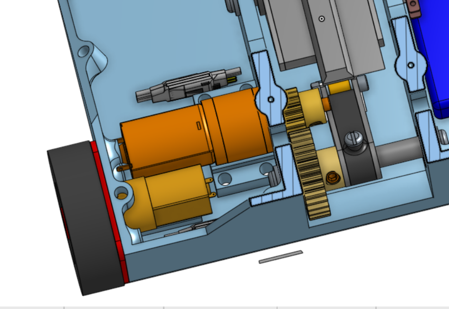
Trying to fit the gearmotor in the bot, it was clear I'd still need some geartrain between the motor and the trigger shaft to offset the two for packaging. Using the gears available on ServoCity, the lightest gear train I could get to fit had a 2:1 ratio. This means the gearmotor torque requirement would be cut in half and I would have a large range of speeds to select from as most of the series of motors would provide enough torque and all weigh roughly the same amount.
The next step was making sure everything still fit in the 1lb weight limit. Below is the updated weight spreadsheet. The biggest change is that in order to make weight for the bigger gear motor, the wedges had to be thinned out to 1mm from 1/16" (1.6 mm) before. This is a little thinner than I'd want it to be but with how cheap the spares are, they could be considered more expendable and be replaced after a few battles. Everything is basically the same size and layout.
The next step was making sure everything still fit in the 1lb weight limit. Below is the updated weight spreadsheet. The biggest change is that in order to make weight for the bigger gear motor, the wedges had to be thinned out to 1mm from 1/16" (1.6 mm) before. This is a little thinner than I'd want it to be but with how cheap the spares are, they could be considered more expendable and be replaced after a few battles. Everything is basically the same size and layout.
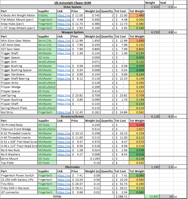
I don't have enough weight for two springs, but the single spring should be plenty of flipping power. It will be close to the weight limit, but I should be able to make it work.
There were some other minor improvements that I made to the bot. In my testing I realized that I needed to put a hard stop to limit the travel of the flipper arm so that it doesn't continue to swing until it wedges itself against the base plate. To limit this, I added some holes to glue a thin piece of piano wire in the bot across the flipper assembly to stop the arm from over swinging. The other part of this is that the flipper arm needs to have some spring return to push it back down after the trigger travels underneath it to grab the underside. The central spacer pushes the leaf spring back up as the trigger rotates down. This will spring load the arm down to limit the amount of time the arm is in an upright position and vulnerable.
There were some other minor improvements that I made to the bot. In my testing I realized that I needed to put a hard stop to limit the travel of the flipper arm so that it doesn't continue to swing until it wedges itself against the base plate. To limit this, I added some holes to glue a thin piece of piano wire in the bot across the flipper assembly to stop the arm from over swinging. The other part of this is that the flipper arm needs to have some spring return to push it back down after the trigger travels underneath it to grab the underside. The central spacer pushes the leaf spring back up as the trigger rotates down. This will spring load the arm down to limit the amount of time the arm is in an upright position and vulnerable.
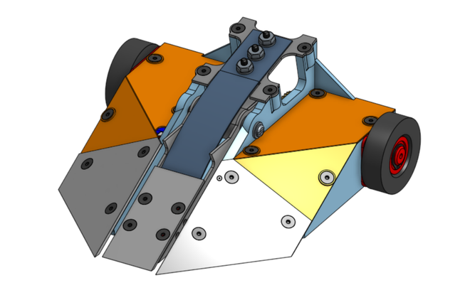
That mostly covers the general design work for 1.1. There were some additional weight reductions added, but nothing worth addressing. Below is a picture of the final 1.1 CAD
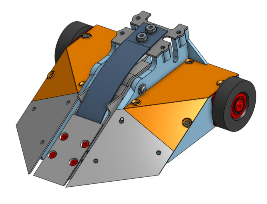
v1.1 Build
In order to keep this post shorter, I'm going to only lightly go into the build log for v1.1 of Drop Test. Most of the build is the same as the first version, with a few minor changes. I've included a quick gallery below of the build including a few closeups of some of the changes
Knowing that I could get withing the 16oz weight limit, I could revisit some compromises I made in the design process to see if I could make weight for some of these small improvements. These included extra top armor and a bigger battery. The top armor I had was 1/32" 3D printed NylonX, which is paper thin and really only serves the purpose of holding the electronics in and doesn't really provide protection from anything. I had some 1/16" UHMW that I had Lying around that would both be slightly improved top armor and be semi translucent so the lights on the ESCs would serve as the power indicator lights. These would be heavier though and I would need to make weight for them somewhere as I was at the limit already.
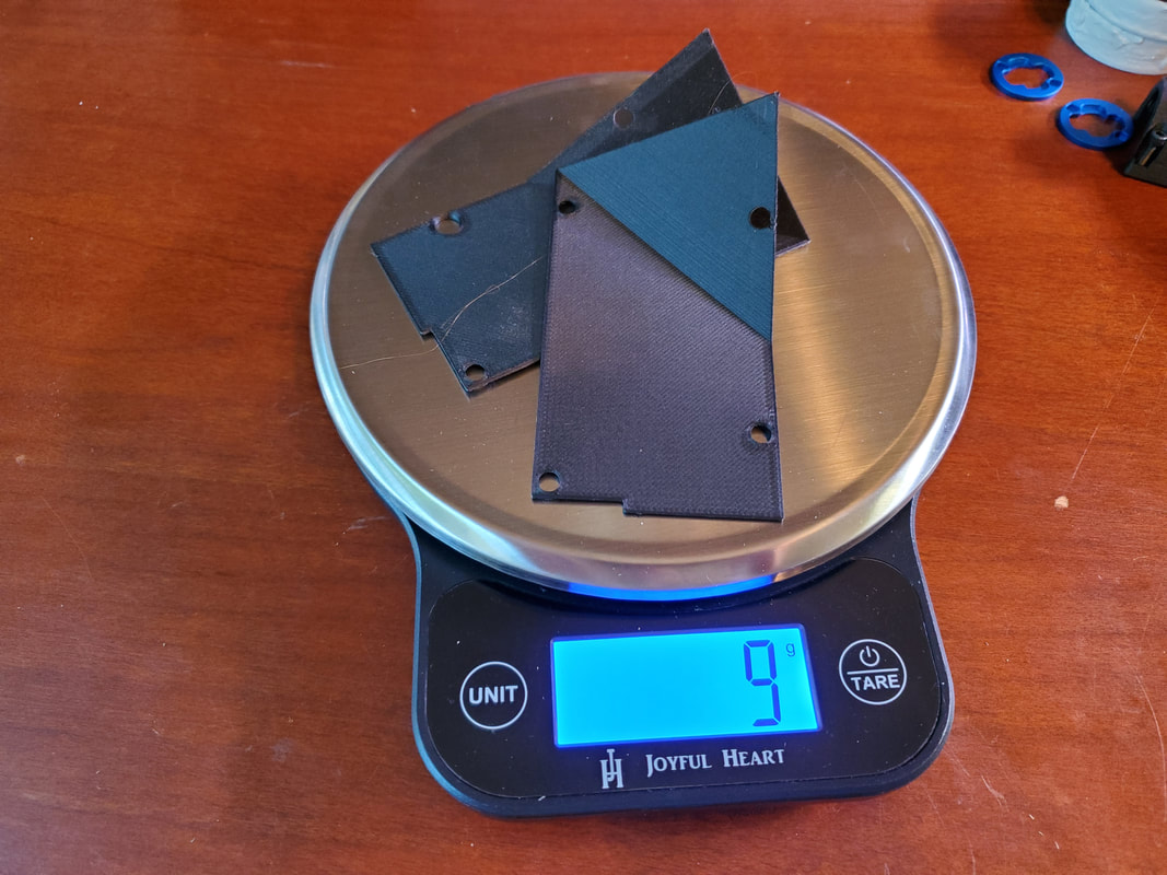 | 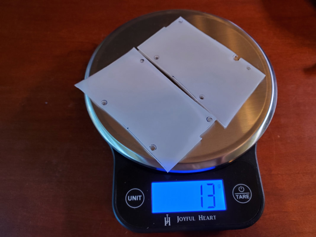 |
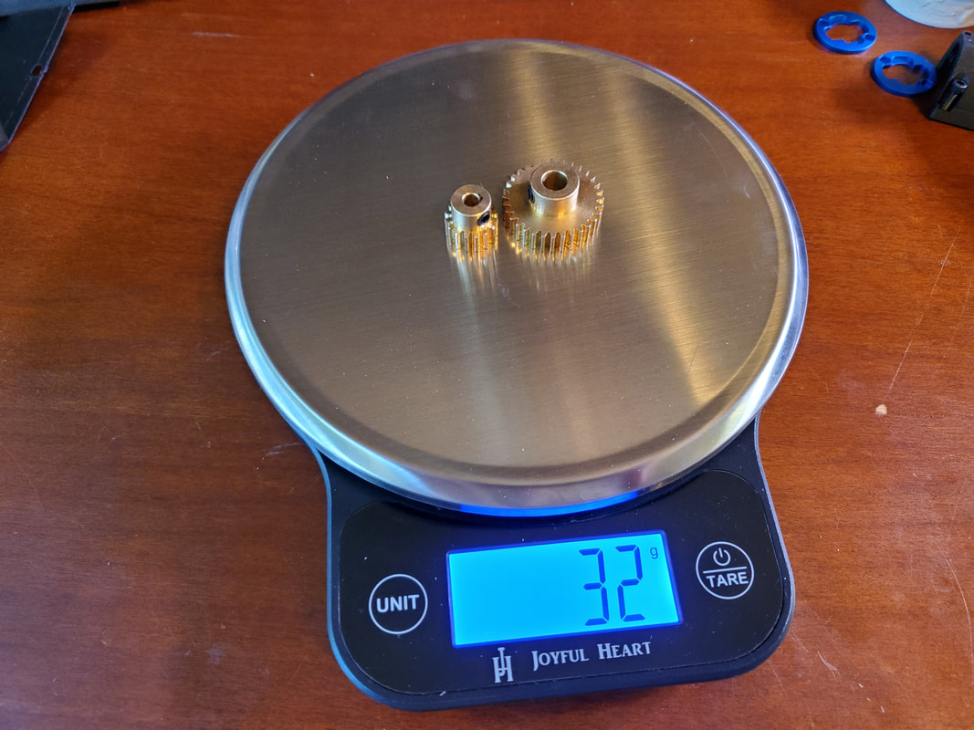
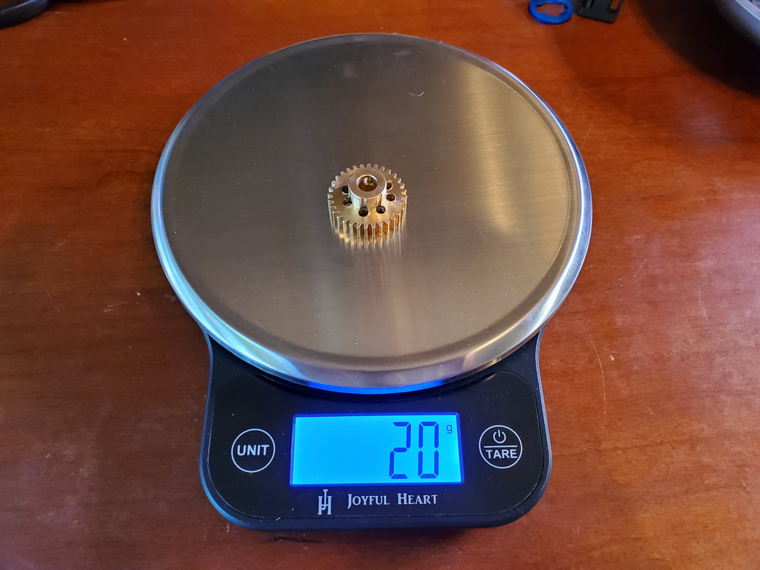
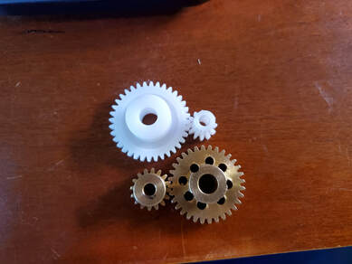
4 grams is a small price to pay to have something reasonable for top armor. It's not going to stop any direct hits, but the risk of spilling the electronics everywhere after a hit has decreased significantly. Those 4 grams had to come from somewhere though. The first place I started with was the weapon gears. These gears are pretty hefty, being made of brass, and likely overkill for their given application. Together they weigh in at 32g which is 7% of the robot's total weight which is a lot given that the top armor weighs only 13g all together. There was already some weight reduction done to the gears by the manufacturer, but I figured I could drill a couple of holes in the big one at least and get back a few grams. Drilling holes into the big gear saved 2g from the total weight, which is less than I'd hoped for but still something. I had a radical backup plan of switching the gears to plastic instead of brass which would have saved 26g which is almost a full ounce of weight. But after looking at the gears, I decided against it as I'd be concerned about their durability in combat. I'd have to find the weight elsewhere. I definitely plan to revisit this in the future, probably replace the gears with a timing belt. Now that the driving gear doesn't have to connect to a servo, I can same some of that weight and give move space for the motors by swapping the gears for a timing belt.
 |  |
The other item on my list to add was a bigger battery. I had originally wanted to use a 3s 11.1V battery for the speed in the drive motors, but the servo I had was only rated to 2s and I didn't really have weight for a BEC to reduce the voltage to a reasonable level. So I had planned to use a 2s battery for everything. But now that the servo is out, the new gearmotor can handle up to 18V. So I can run the whole bot off 3s without a problem.
I had received a new TinyESC from Fingertech and installed it, but the 65RPM motor I had in there just didn't seem to have enough power to reliably fire the flipper. As such, I ordered some of the 33RPM version that theoretically have double the torque. Running these motors on 3s is enough to flip really consistently, but the motor itself doesn't seem to have significantly more torque than the 65RPM version. Being that I need to find a few final grams to shave off, I need to test if the 65 RPM motor would be enough on 3s as the 33 RPM motor is slightly heavier. This would also allow the weapon to reload more quickly which would be very helpful.
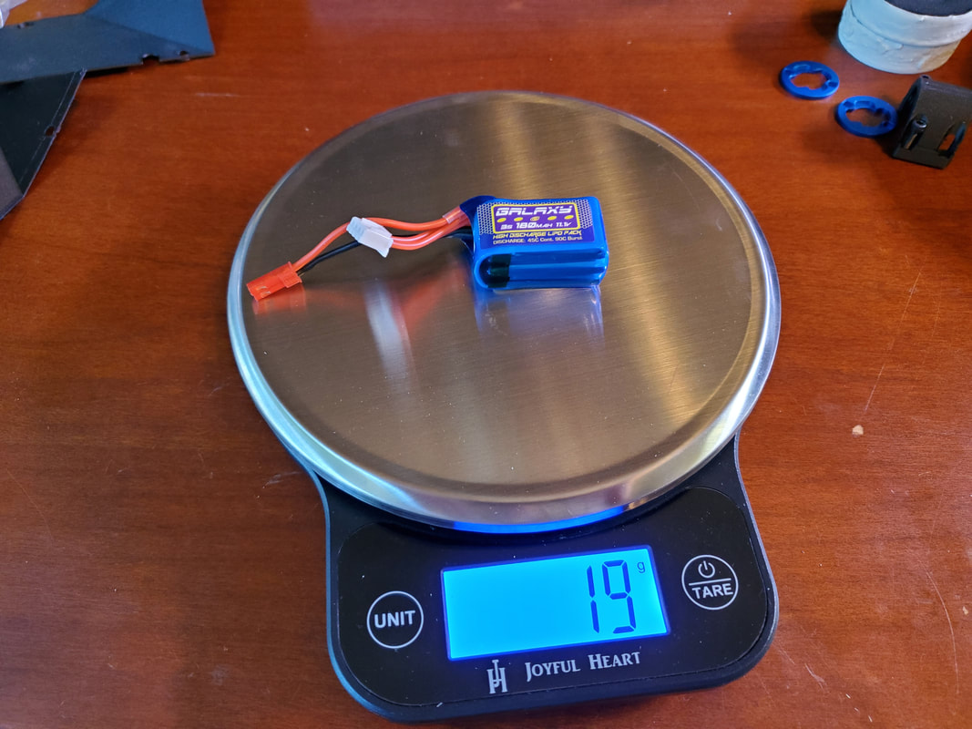
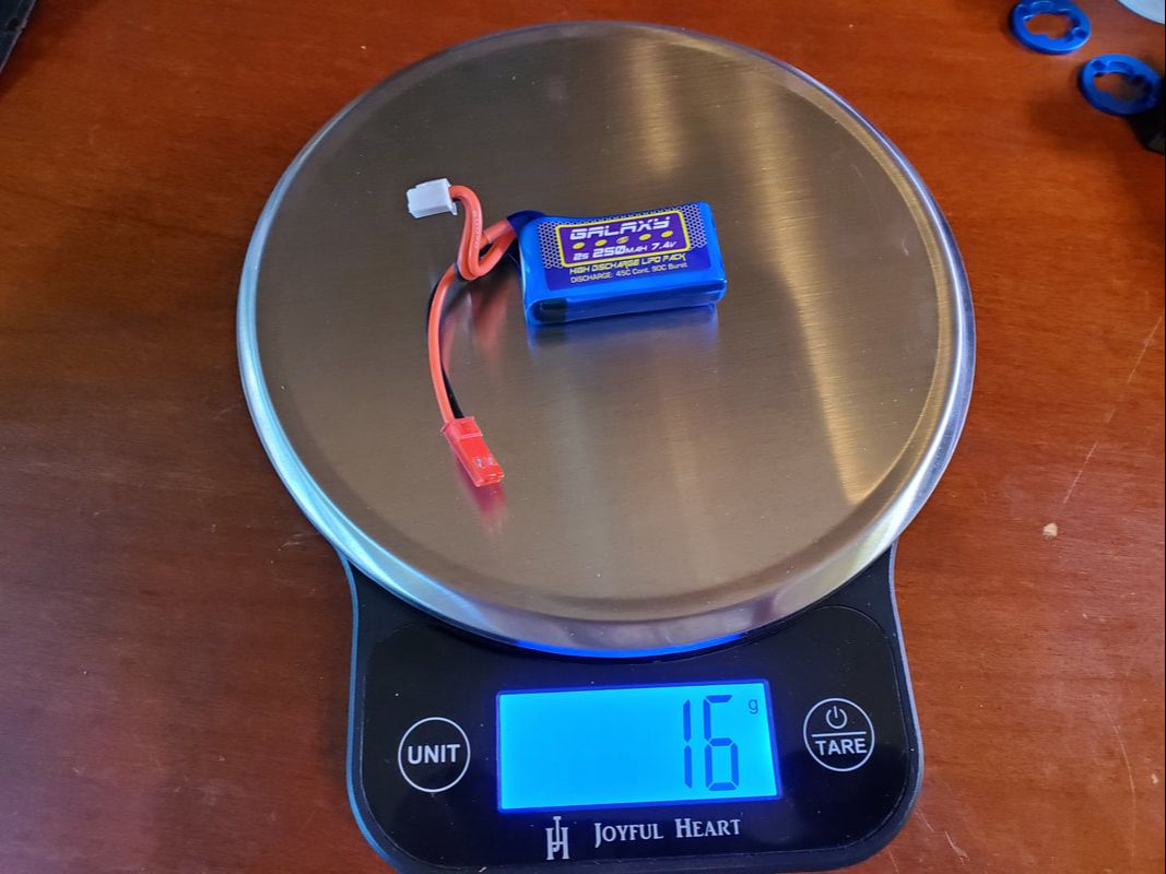
I have a sampling of all of the small batteries that fingertech sells in 2s and 3s for this project to test. Ideally I could use a smaller 3s battery that has lower capacity than the 2s battery I was planning to use as the higher voltage would mean the robot would use less amperage as the power consumption is based off the combination of voltage and amperage. I will have to test the bot out to see if the 3s 180 mAh pack I plan to use is enough to get the bot through a full 3 min fight.
I had received a new TinyESC from Fingertech and installed it, but the 65RPM motor I had in there just didn't seem to have enough power to reliably fire the flipper. As such, I ordered some of the 33RPM version that theoretically have double the torque. Running these motors on 3s is enough to flip really consistently, but the motor itself doesn't seem to have significantly more torque than the 65RPM version. Being that I need to find a few final grams to shave off, I need to test if the 65 RPM motor would be enough on 3s as the 33 RPM motor is slightly heavier. This would also allow the weapon to reload more quickly which would be very helpful.
I have a sampling of all of the small batteries that fingertech sells in 2s and 3s for this project to test. Ideally I could use a smaller 3s battery that has lower capacity than the 2s battery I was planning to use as the higher voltage would mean the robot would use less amperage as the power consumption is based off the combination of voltage and amperage. I will have to test the bot out to see if the 3s 180 mAh pack I plan to use is enough to get the bot through a full 3 min fight.
 |  |
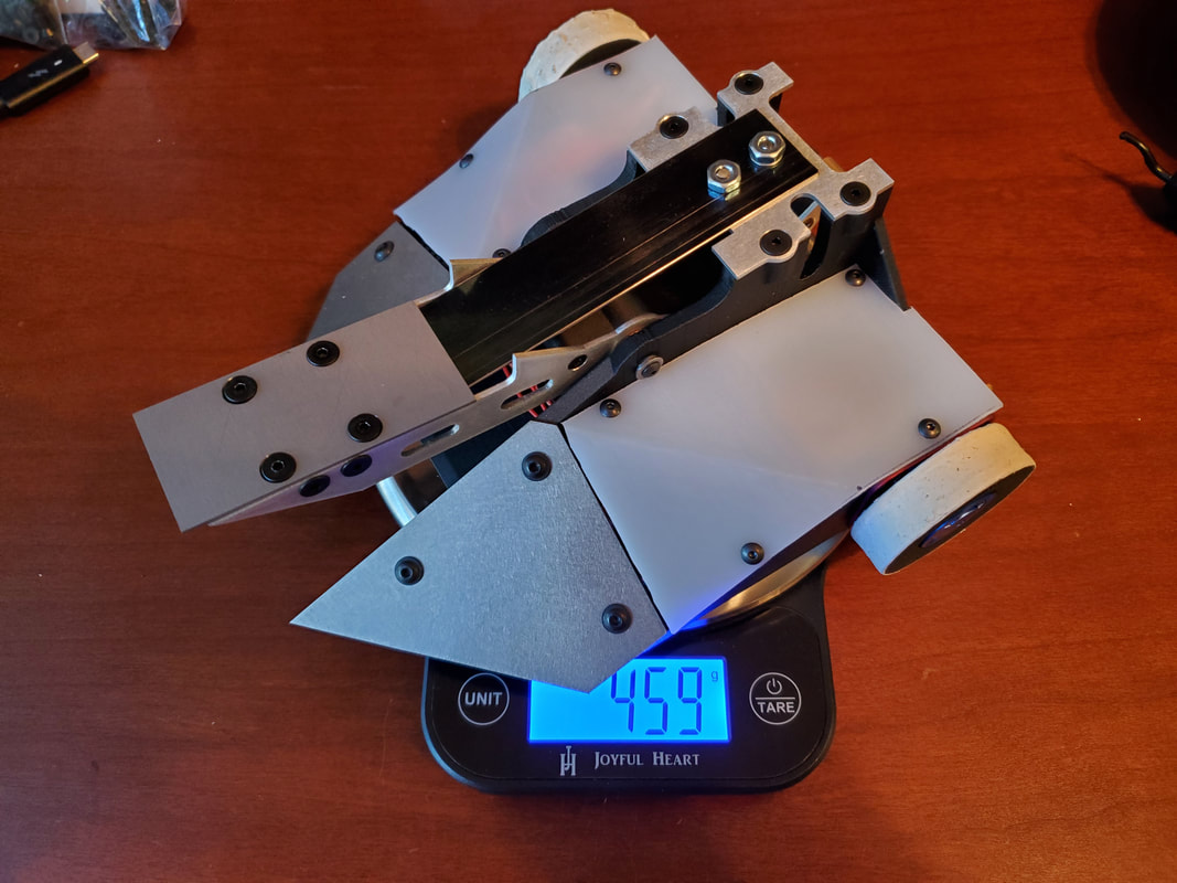
With all of these small changes the bot comes in around 6g over weight. I think I can pretty easily make up this weight. I still need to grind down the wedges. I think I can also make up a decent amount of weight by tidying up the wires and trimming a few other things. I will call it good enough for now and make the changes after I trim down the metal pieces if necessary.
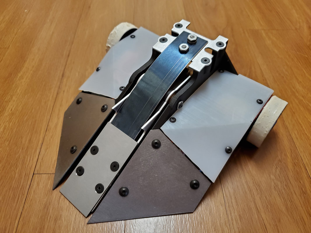
That being said I am going to call this project done as far as this blog goes. None of the changes I make from here on out will change any of the looks or function. Just minor adjustments to make weight. For now, until I can find an event to go to, here's some photos and a test video.
That being said I am going to call this project done as far as this blog goes. None of the changes I make from here on out will change any of the looks or function. Just minor adjustments to make weight. For now, until I can find an event to go to, here's some photos and a test video.
 RSS Feed
