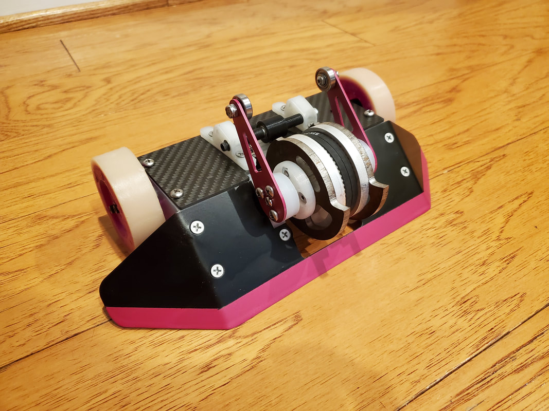
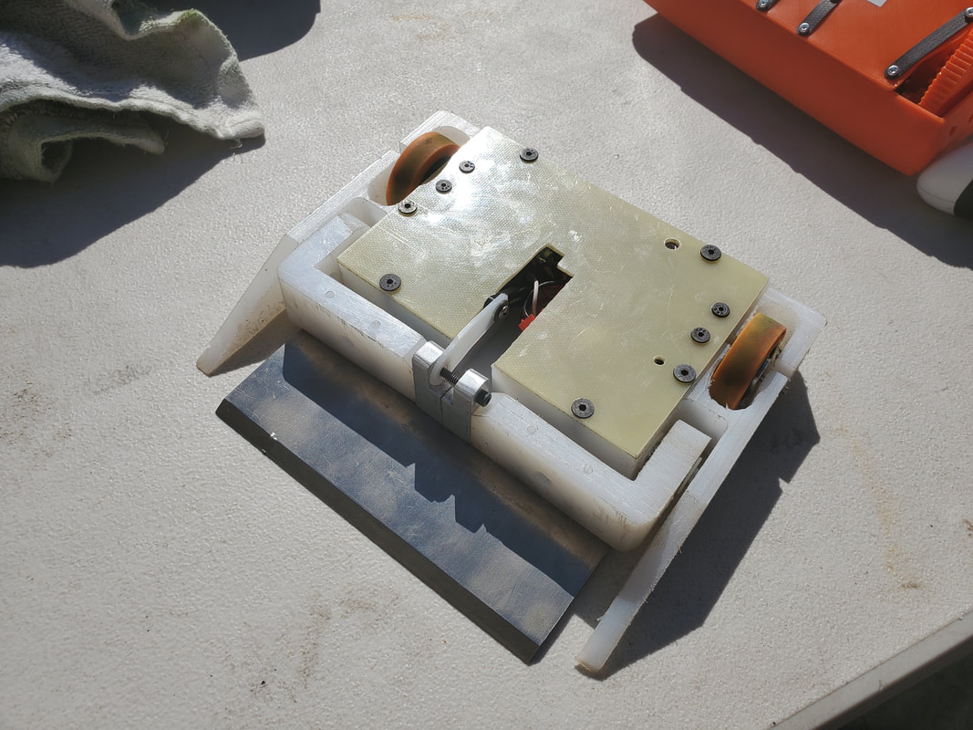
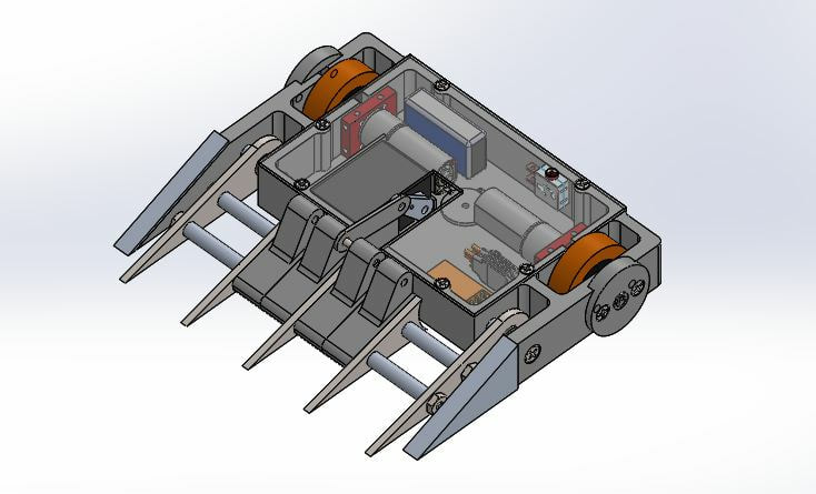
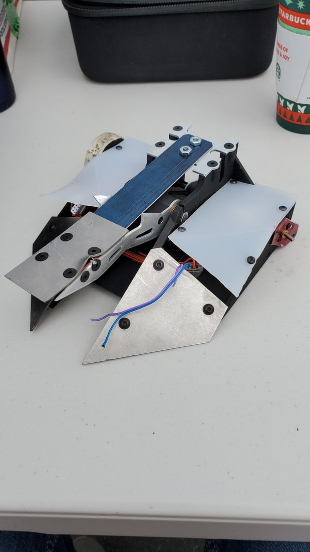
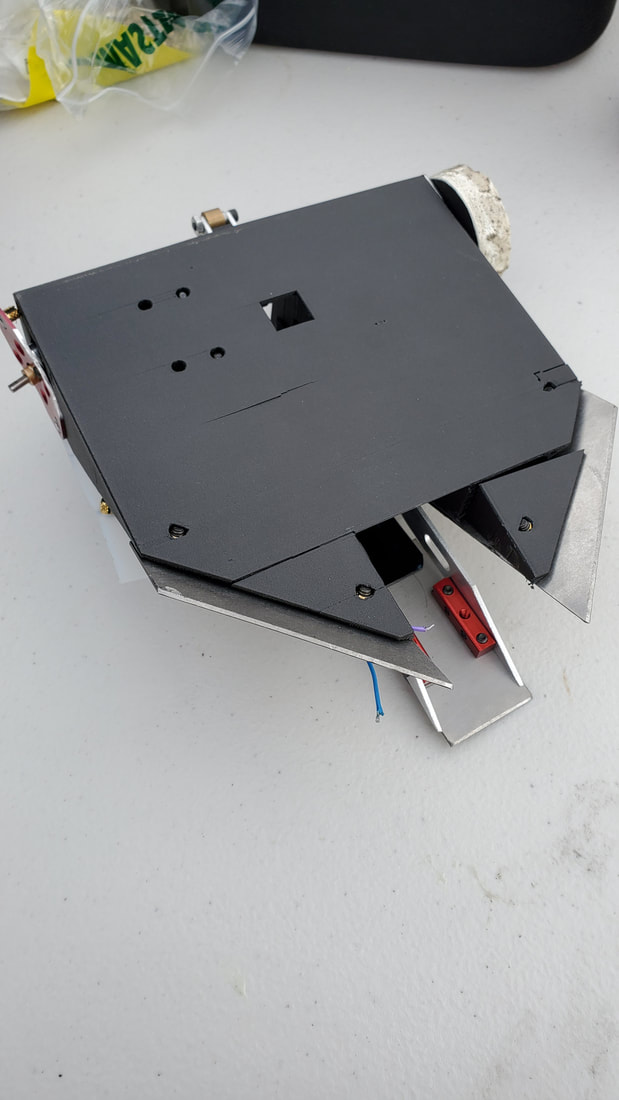
Drop Test
Drop Test vs Cheddar (L)
First fight of the tournament for Drop Test. Cheddar was a powerful vertical spinner. From the Brazilian team that showed up. Driven very well and aggressively. I missed an opportunity early to get a good flip in, but it didn't matter. The first major impact that occurred, broke the flipper trigger mechanism and landed me upside down, for a quick knockout.
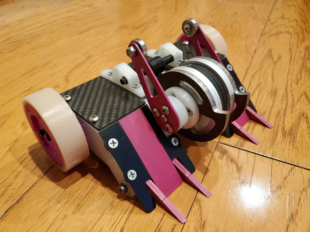
Drop Test vs Peacemaker (W)
I really wish I had a video of this fight. One of the best performances I've had with Drop Test. Peacemaker was a Fingertech Viper vertical spinner kit. Drop Test got under them easily and got in a bunch of flips over the course of the fight. At one point I picked up the other bot while resetting the flipper mechanism and showing off for the judges. Easy win by judges decision
Drop Test vs Wedge 1 Wedge 2 (W)
I was a little nervous for this fight as Hercules had faced Wedge 1 Wedge 2 a year or two ago in LA. They're not damaging, but with good drivers, they're pesky enough to control a fight and win by a decision. Drop Test had a little more "damage" than Hercules does and was able to control the fight a bit better. Close win by judges decision.
Drop Test vs Flex (W)
Flex is one of m favorite robots of all time. It's builder brought it out of retirement for Robogames this year. The design is a clamping lifter that I at one point tried to coy with Hercules. Very creative design, much like Drop Test that allows for lots of control, and a non damaging fight. Lots of fun, and a split judges decision for Drop Test.
Drop Test vs Thagomizer (L)
I was dreading this matchup. There was virtually no chance that I'd win this if Thagomizer was working, and he'd had a full day to prepare from his loss. Drop Test had no real side armour, so I had to try and react to his classic spin move in time to block it, for the full match. Obviously this plan falls apart as you start losing wheels. Loss by KO for Drop Test, to knock it out of the tournament.
Drop Test vs Sidekick (W)
This was a fun grudge match against one of m co-workers who also attended the event. Just for fun, but I still feel like I won. His crab drive antweight was still really impressive and surprisingly difficult to control against.
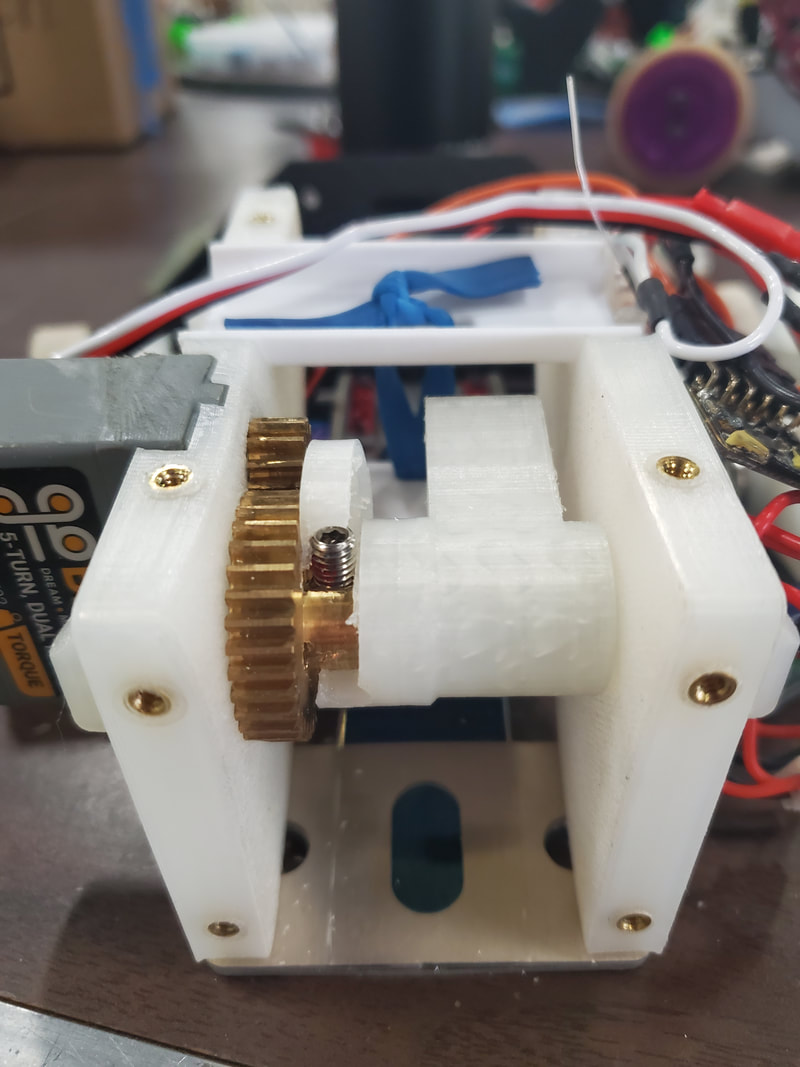
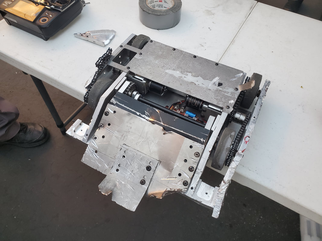
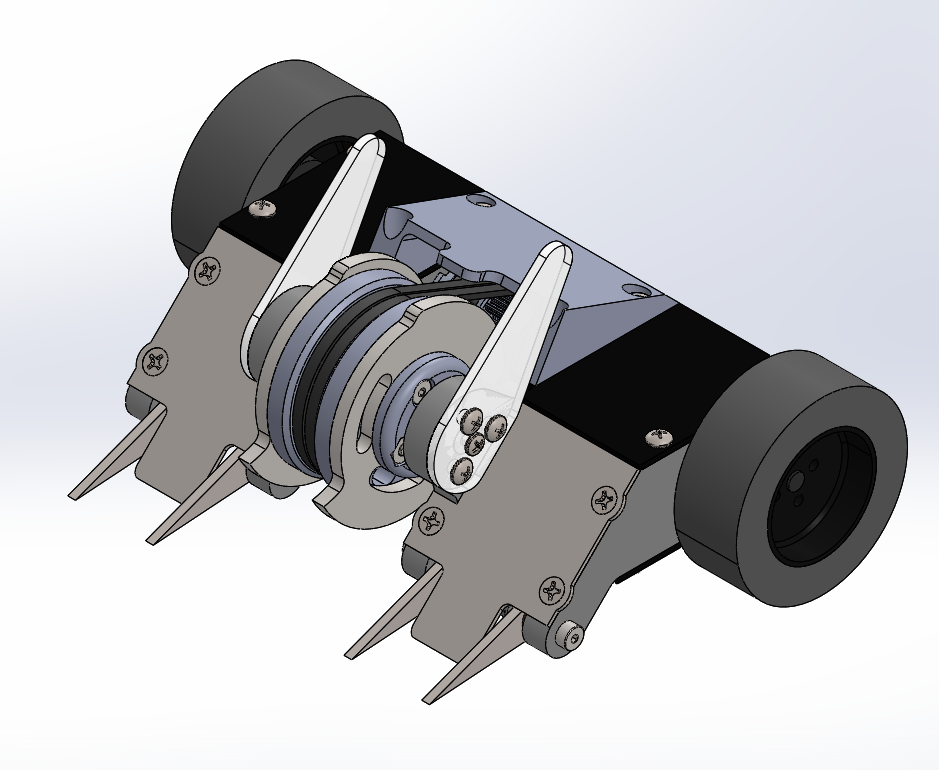
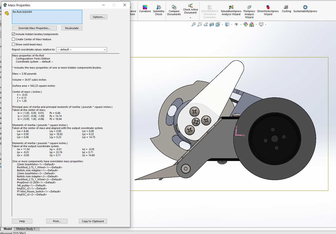
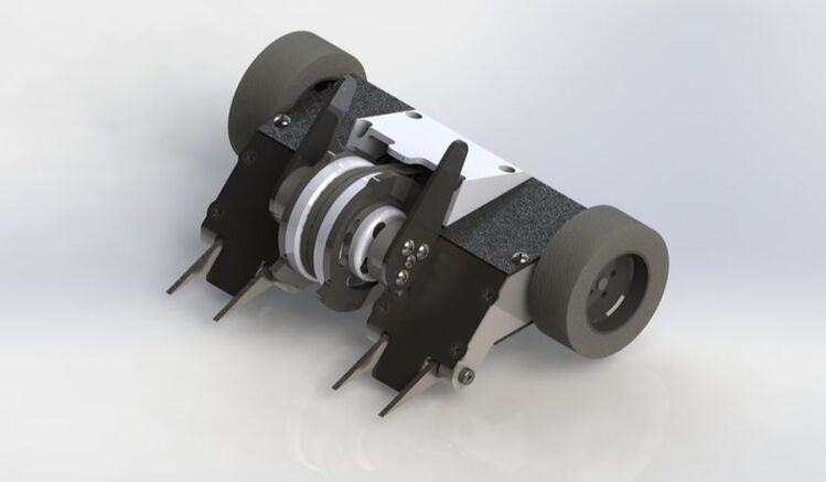
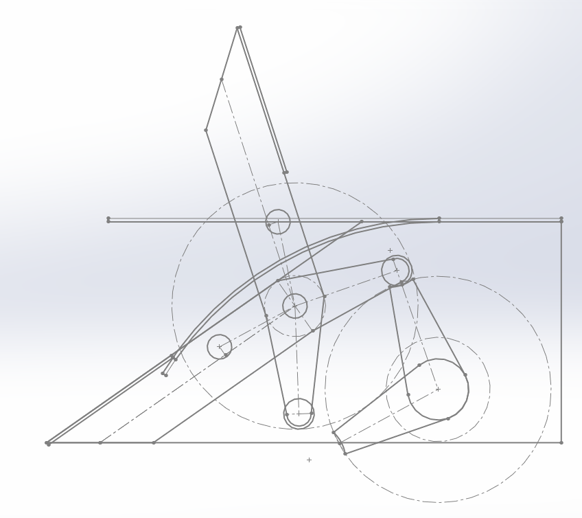
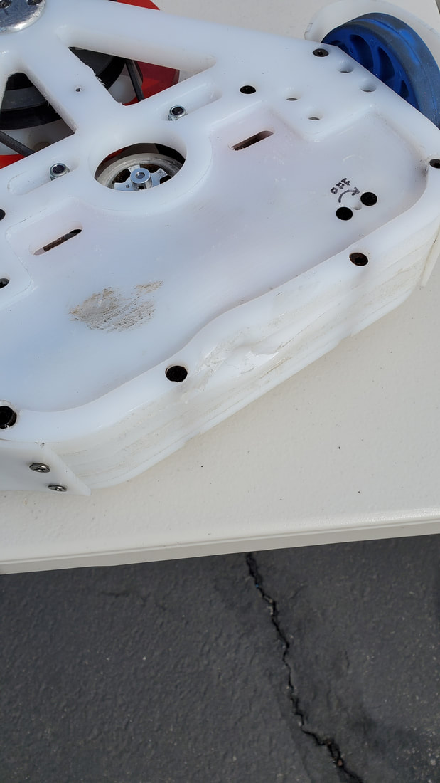
Re-Roll
Re-Roll vs Blue Lion (W)
This was the first fight of the entire tournament. As such, I was a little rushed and didn't have time to record it. But being the first fight, there was a decent crowd, including a news crew there to report on Robogames. As such, they recorded some of the match for their piece, and even interviewed me after about the win. Link to the article
Re-Roll vs Duct Spartan (W)
Second fight for Re-Roll against a D2 kit. Was actually a little worried about this one, as Re-Roll's drive was lackiing in the first fight. So I knew I'd have to win on damage. The thing that saved the fight for me was taking off one of their wheels. Win for Re-Roll on a judges decision. Link to video
Re-Roll vs Badbot (W)
Badbot was a Vector horizontal spinner kit bot. Re Roll took out the belt early. When they got stuck on the wall, they tapped out to avoid more damage. Third straight win for Re-Roll.
Re-Roll vs Mean Bean (L)
Mean Bean is a classic Fingertech Beater Bar spinner. It was a very solid bot, and Re-Roll just couldn't keep up. It was out-classed in weapon and drive speed. If I want to be competitive, I need to be able to beat this type of robot. Definitely some things to improve. But Re-Roll still put up a good fight. Loss by KO
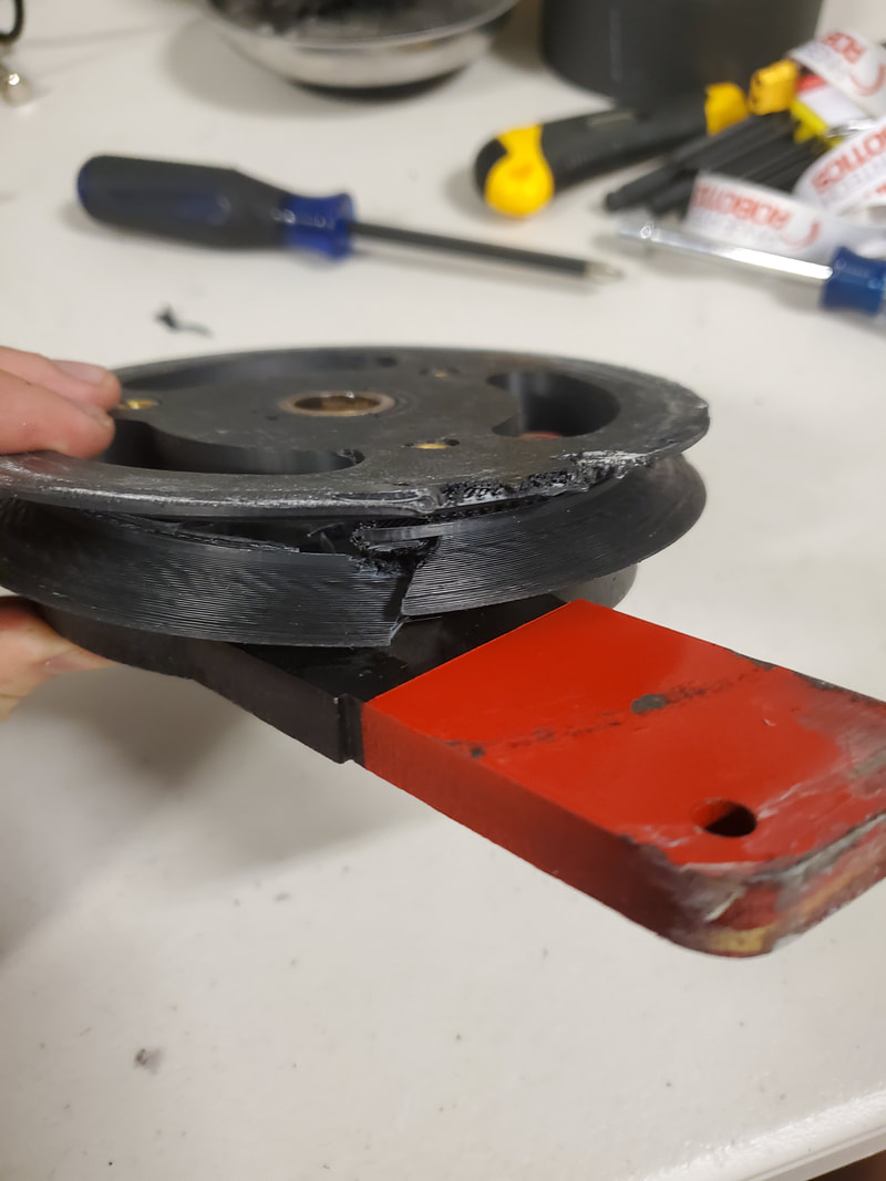
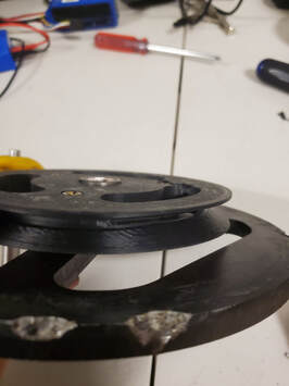
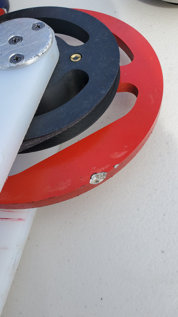
Re-Roll vs Killicake (L)
Killicake was a gorgeous full body spinner. The entire outer ring was made of 1.5" AR500 and hit like a tank. Only strategy I had was to slowly back it into a corner hoping to get it to stop spinning long enough to damage it's underside. But an early collision took out one of my wheels and the fight was basically over from there. Final loss of the tournament by knockout.
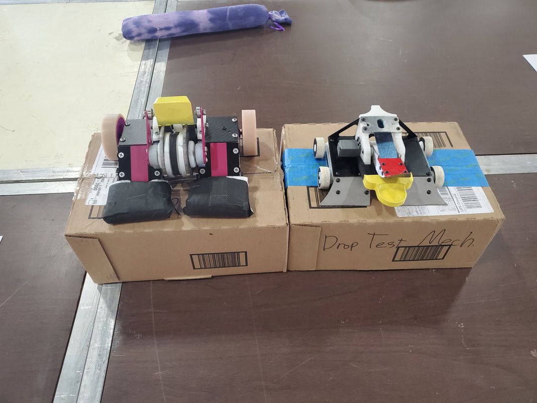
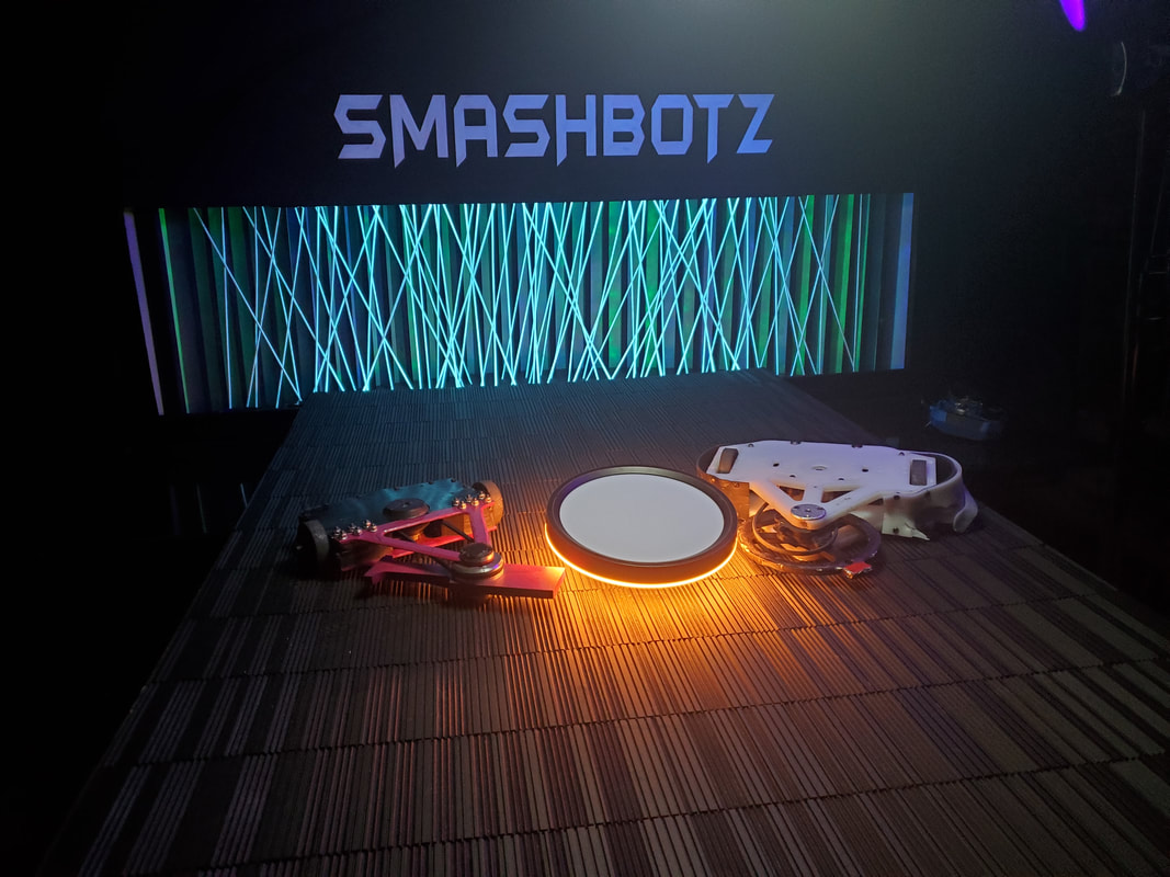
Overall I'm very happy with how both bots did. Both finished 3-2 on the weekend. For Re-Roll, I have some upgrades in mind, but will take some time to implement them. The design has a lot of potential, but needs some serious improvements to be competitive in modern beetleweights. For Drop Test, I think I've hit the point of learning enough at the small weight classes to start scaling it up. I plan to work towards creating a 30lb sportsman version that should not only be more competitive, but less likely to receive significant damage, as durability is one of the major downsides of the design.


 RSS Feed
